Screwdriving tool and tool holder for such a screwdriving tool

A tool and tool head technology, applied in the direction of tool joints, tool holder accessories, tool workpiece connections, etc., can solve the problems of outer wall deformation, axial orientation influence, limited centering effect, etc.

Active Publication Date: 2014-10-08
FRANZ HAIMER MASCHINENBAU KG
View PDF10 Cites 4 Cited by
  • Summary
  • Abstract
  • Description
  • Claims
  • Application Information

AI Technical Summary

Problems solved by technology

In the first alternative, although a precise axial positioning of the screw-in tool inside the receptacle is achieved by the plane of the radial flange, the centering effect by the cylindrical contact surface is limited
Although an improved centering effect can be achieved by the conical contact surface, the outer wall of the tool holder can, however, be deformed outwards due to the wedging action of the conical contact surface, which can have a negative effect on the axial orientation

Method used


Image

  • Screwdriving tool and tool holder for such a screwdriving tool
  • Screwdriving tool and tool holder for such a screwdriving tool
  • Screwdriving tool and tool holder for such a screwdriving tool

Examples


Embodiment Construction

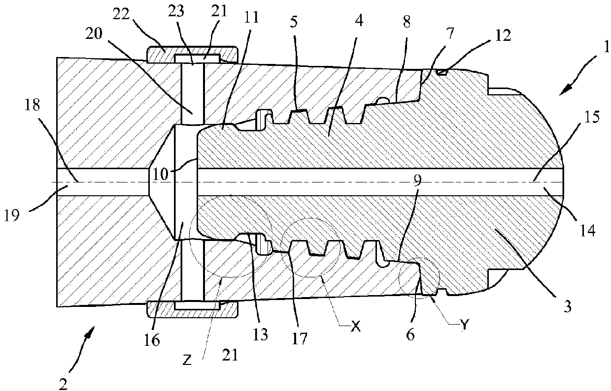
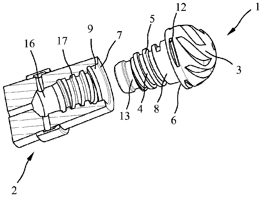
[0028] exist figure 1 and 2 The figure shows a tool assembly with a screw-in tool 1 and an associated tool receptacle 2 in longitudinal section and in perspective view. The screw-in tool 1 has a tool head 3 designed here as a ball-nose milling cutter and a conical, rearwardly tapering tool shank 4 with an external thread 5 . Provided between the tool head 3 and the external thread 5 is a first support region with a conical first contact surface 6 for bearing against a corresponding conical surface on the front side of the tool receptacle 2 . and a second conical contact surface 8 for abutting against a second conical bearing surface 9 inside the tool receiving device. This results in a double-cone structure at the transition between tool head 3 and external thread 5 , which double-cone structure serves for improved centering and increased support. A second support region 11 is provided on the free rear end 10 of the tool shank 4 .

[0029] as specified by figure 2 Conseq...


PUM


Abstract

The invention relates to a screwdriving tool (1) and to a tool holder (2) for such a screwdriving tool. the screwdriving tool (1) contains a tool head (3) and a tool shank (4) having an outer thread (5) and a supporting region arranged between the tool head (3) and the outer thread (5). according to the invention, the supporting region is formed by two conical bearing faces (6, 8) having different cone angles.

Description

technical field [0001] The invention relates to a screw-in tool / screw drive tool according to the preamble of claim 1 . The invention also relates to a tool receptacle for such a screw-in tool and a tool assembly with a screw-in tool and a tool receptacle. Background technique [0002] WO 2006 / 033617 A1 discloses a screw-in tool comprising a tool head and a tool shank with an external thread and a first support region arranged between the tool head and the external thread. In this known screw-in tool, the first support region is designed either as a radial collar with a planar and cylindrical inner contact surface or as a conical contact surface. In the first alternative, although a precise axial positioning of the screw-in tool within the receptacle is achieved by the plane of the radial flange, the centering effect by the cylindrical contact surface is limited. Although an improved centering effect can be achieved by the conical contact surface, the outer wall of the too...

Claims


Application Information

Patent Timeline
Patent Type & Authority Applications(China)
IPC IPC(8): B23B31/11
CPCB23B2265/08B23B2240/24B23C5/1009B23B2231/02B23C2210/02B23B29/04B23B2240/00Y10T408/45B23C5/26B23C2240/32B23C2250/12Y10T408/95B23B2231/24B23B2260/1381Y10T408/89B23B31/1115Y10T279/16Y10T408/90993B23B31/08B23B31/11B23B51/12B23P19/06B25B21/00B25B23/02
Inventor F·海莫
Owner FRANZ HAIMER MASCHINENBAU KG
Why Eureka
Try Eureka