Car position detection device
A car position detection, car technology, applied in the direction of transportation and packaging, elevators, etc., to achieve the effect of reducing manufacturing costs
- Summary
- Abstract
- Description
- Claims
- Application Information
AI Technical Summary
Problems solved by technology
Method used
Image
Examples
Embodiment approach 1
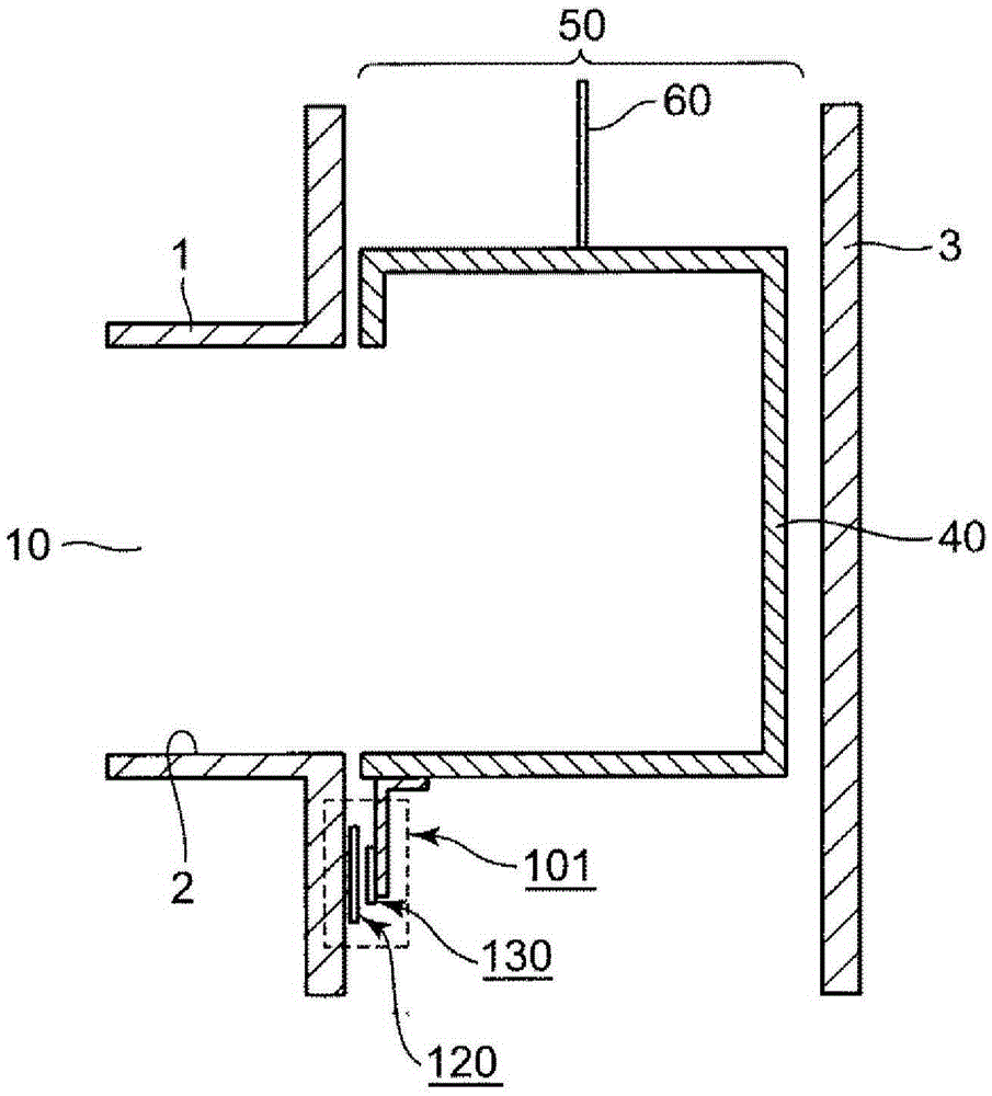
[0049] figure 1 It is a diagram showing a schematic configuration of an elevator provided with the car position detection device 101 according to the first embodiment, and shows a state in which the car 40 on which passengers ride is located at the hall entrance 10 . Such an elevator uses a rope 60 to connect the car 40 to a counterweight (not shown), and uses a motor (not shown) to wind up and unwind the rope 60 to lift the car 40 in the hoistway 50 . In addition, the landing entrance 10 is composed of the landing ceiling 1 and the landing floor 2 , and the hoistway 50 is formed by the landing opening 10 and the side wall 3 . In addition, the position of the car 40 can be detected by counting incremental pulses output from an encoder connected to the above-mentioned motor. In addition, as described above, the pulse count value is reset when the car position detection device 101 detects the door zone, and then the motor is controlled using the set value to stop the car 40 at ...
Embodiment approach 2
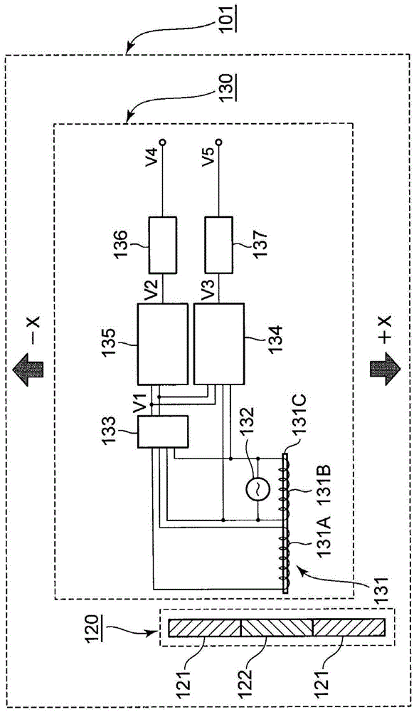
[0089] use Figure 13 , the car position detection device according to Embodiment 2 of the present invention will be described. Such as Figure 13 As shown, in the car position detection device 102 according to Embodiment 2, a detection coil 131A and an exciting coil 131B are arranged in a direction perpendicular to the ascending and descending direction with the identification plate 120 interposed therebetween. Such structure and reference Figure 9 The structure described in the car position detection device 101 of Embodiment 1 is the same, however, Figure 9 sensor 130 shown with Figure 13 The structural difference of the illustrated sensor 130-4 is that the Figure 9 The alternating magnetic field component removal circuit 133 is shown.
[0090] In such a configuration, the detection coil 131A outputs a voltage obtained by combining the alternating magnetic field and the eddy current magnetic field.
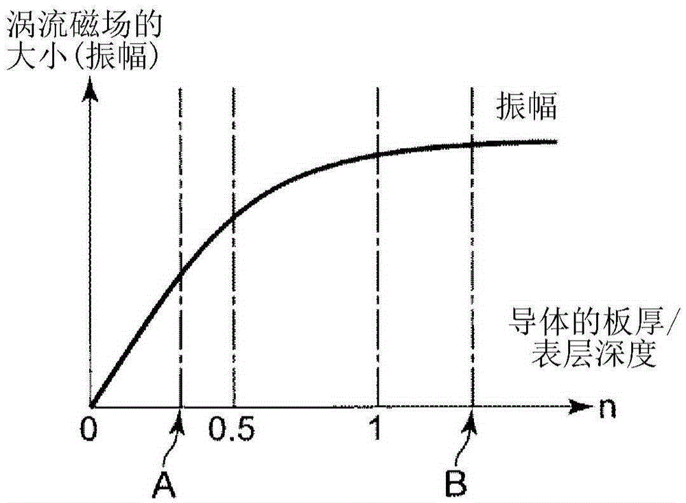
[0091] Figure 14A The ratio n(= d / δ) relationship between, F...
Embodiment approach 3
[0103] Next, refer to Figure 18 , the car position detection device 103 according to Embodiment 3 of the present invention will be described.
[0104] The car position detection device 103 of Embodiment 3 has the same structure as that of the car position detection device 101 of Embodiment 1 described above. However, in the car position detection device 103 of Embodiment 3, the comparator 137 has It differs from the car position detection device 101 of Embodiment 1 in that there are two thresholds. Hereinafter, the different parts will be described in detail.
[0105] When the sensor 130 moves toward the identification plate 120 from outside the range of the identification plate 120, for example, in the +X direction, the identification plate 120 is the same as that in Embodiment 1, therefore, as Figure 18 As shown, the output V3 of the phase difference detection circuit 134 and the output V2 of the amplitude value detection circuit 135 change. The output V2 of the amplitu...
PUM
 Abstract
Description
Claims
Application Information
 - R&D
- Intellectual Property
- Life Sciences
- Materials
- Tech Scout
- Unparalleled Data Quality
- Higher Quality Content
- 60% Fewer Hallucinations
Browse by: Latest US Patents, China's latest patents, Technical Efficacy Thesaurus, Application Domain, Technology Topic, Popular Technical Reports.
© 2025 PatSnap. All rights reserved.Legal|Privacy policy|Modern Slavery Act Transparency Statement|Sitemap|About US| Contact US: help@patsnap.com


