Capacitive touch panel

A technology of electrostatic capacitance and touch panel, which is applied in the fields of electrical digital data processing, instrumentation, calculation, etc., and can solve the problems of lower transmittance, higher cost, and difficult to see the display.

Inactive Publication Date: 2014-10-08
SMK CO LTD
View PDF7 Cites 3 Cited by
  • Summary
  • Abstract
  • Description
  • Claims
  • Application Information

AI Technical Summary

Problems solved by technology

[0005] The change of the electrostatic capacitance caused by the input operation body being close to a specific detection electrode is very small, and is inversely proportional to the distance between the input operation body and the detection electrode. Therefore, in the electrostatic capacitive touch panel related to Patent Document 1, the detected Many X-side detection electrodes and Y-side detection electrodes for capacitance changes are arranged close to the input operation area near the input operation position, and these detection electrodes are formed of a transparent material so that the display on the rear side can be visually observed. Therefore, similar to the resistive touch panel, there will be a problem that the cost will increase, and the transmittance will decrease, making the display difficult to see clearly.

Method used


Image

  • Capacitive touch panel
  • Capacitive touch panel
  • Capacitive touch panel

Examples


Embodiment Construction

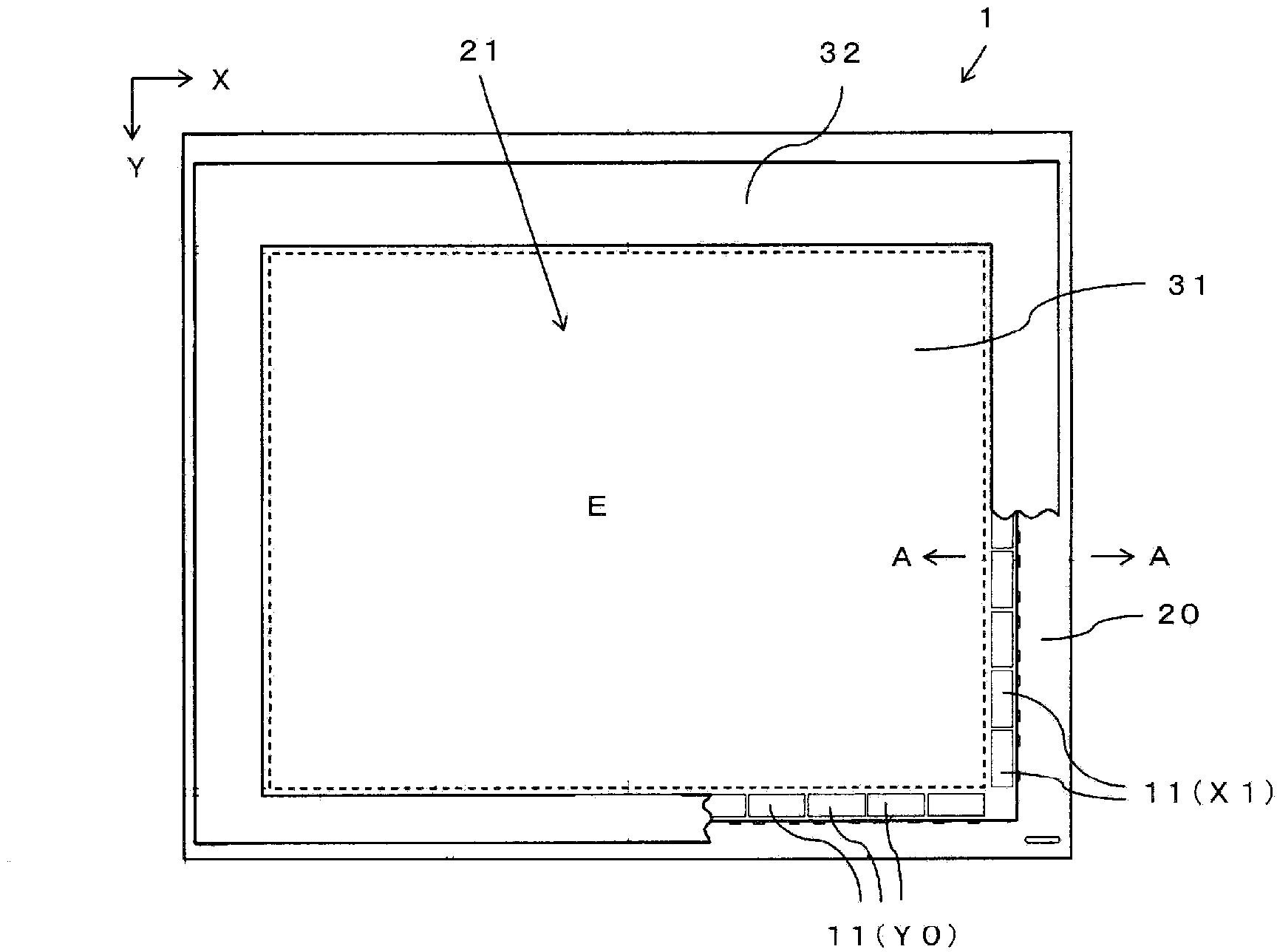
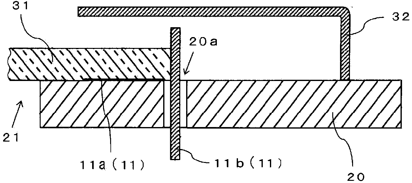
[0094] Below, use Figure 1 to Figure 10 A capacitive touch panel (hereinafter referred to as a touch panel) 1 according to a first embodiment of the present invention will be described. touch panel 1, such as figure 1 , Figure 5 The formula includes: a rectangular frame-shaped insulating substrate 20 with a horizontally long rectangular opening 21 formed in the center, and a plurality of detection electrodes 11, 11 ... formed on the insulating substrate 20 along the periphery of the opening 21 to cover The opening 21 is formed by a transparent glass substrate 31 placed on the insulating substrate 20 with the detection electrodes 11 interposed therebetween, and a shield plate 32 covering the detection electrodes 11 and fixed to the insulating substrate 20 .

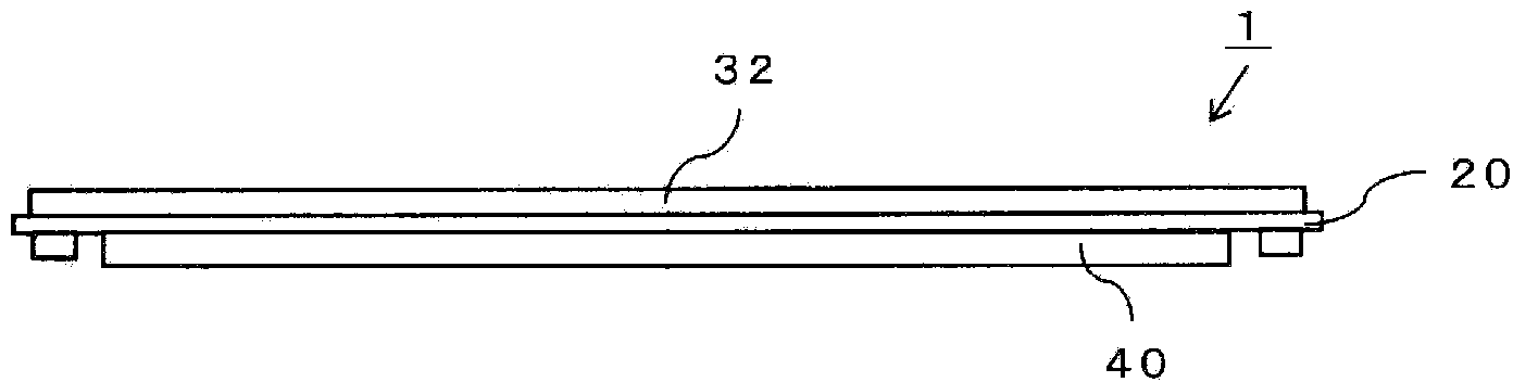
[0095] under the touch panel 1, such as figure 2 As shown, a liquid crystal display module 40 for displaying a specific cursor, icon, etc. is stacked and arranged, and the liquid crystal display module 40 can be view...


PUM


Abstract

A transparent input operation plate with the input operation region inside an opening section formed by a transparent body is supported on an insulating support body appropriately to cover the opening of the opening section. A plurality of detection electrodes is disposed on the insulating support body appropriately to have contact with the transparent input operation plate around the opening section. An AC detection signal with varying relative potential between the input operation body and each detection electrode is sent from a transmission means. Since the reception level of the AC detection signal at a detection electrode is proportional to the electrostatic capacitance that is inversely proportional to the distance between that detection electrode and the input operation body, the relative ratio of the reception levels of the AC detection signals at a group of detection electrodes opposing each other in the opening section is used as a basis to detect the input operation position of the input operation body in the direction in which the detection electrodes oppose each other. Since no detection electrode used for detecting the input operation position is disposed in the input operation region, the detection electrodes can be formed without using transparent conductive material.

Description

technical field [0001] The present invention relates to a capacitive touch panel that is arranged on a display and detects an input operation position of an input operation object such as an icon displayed on the display when a pointer input operation is performed. A capacitive touch panel that detects an input operation position based on the arrangement position of a detection electrode where the capacitance of a finger increases. Background technique [0002] The touch panel used as a pointing device such as an icon displayed on the display of an electronic device has different detection methods for the input operation position, such as electrostatic capacitance method, resistive film method, optical method and other detection methods. The control panel is known. Among them, in the resistive touch panel, a resistive film with a uniform resistance value per unit length is arranged along the input operation surface, and the distance between the detection electrode and the i...

Claims


Application Information

Patent Timeline
Patent Type & Authority Applications(China)
IPC IPC(8): G06F3/044G06F3/041
CPCG06F3/044G06F3/04164G06F3/0446G06F3/04166G06F3/0444
Inventor 南部元俊
Owner SMK CO LTD
Why Eureka
Try Eureka