Multi-axis robot

A multi-axis robot and transmission shaft technology, applied in the field of robots, can solve the problems of inconvenient relocation, inconvenient storage, and large space required.

Active Publication Date: 2014-10-15
HIWIN TECH
View PDF4 Cites 5 Cited by
  • Summary
  • Abstract
  • Description
  • Claims
  • Application Information

AI Technical Summary

Problems solved by technology

[0003] However, by the patent publication figure 1 It can be clearly seen that when the robot is in a stopped state, the arm of the robot needs to be supported by a U-shaped bracket, and the space required is very large. If the arm of the robot is increased, more space will be required to place the robot. When relocating the robot, a larger box is needed to place the robot to avoid the robot being damaged due to collision, so there are problems of inconvenient storage and inconvenient relocation

Method used


Image

  • Multi-axis robot
  • Multi-axis robot
  • Multi-axis robot

Examples


Embodiment Construction

[0033] In order to further explain the technical solution of the present invention, the present invention will be described in detail below through specific examples.

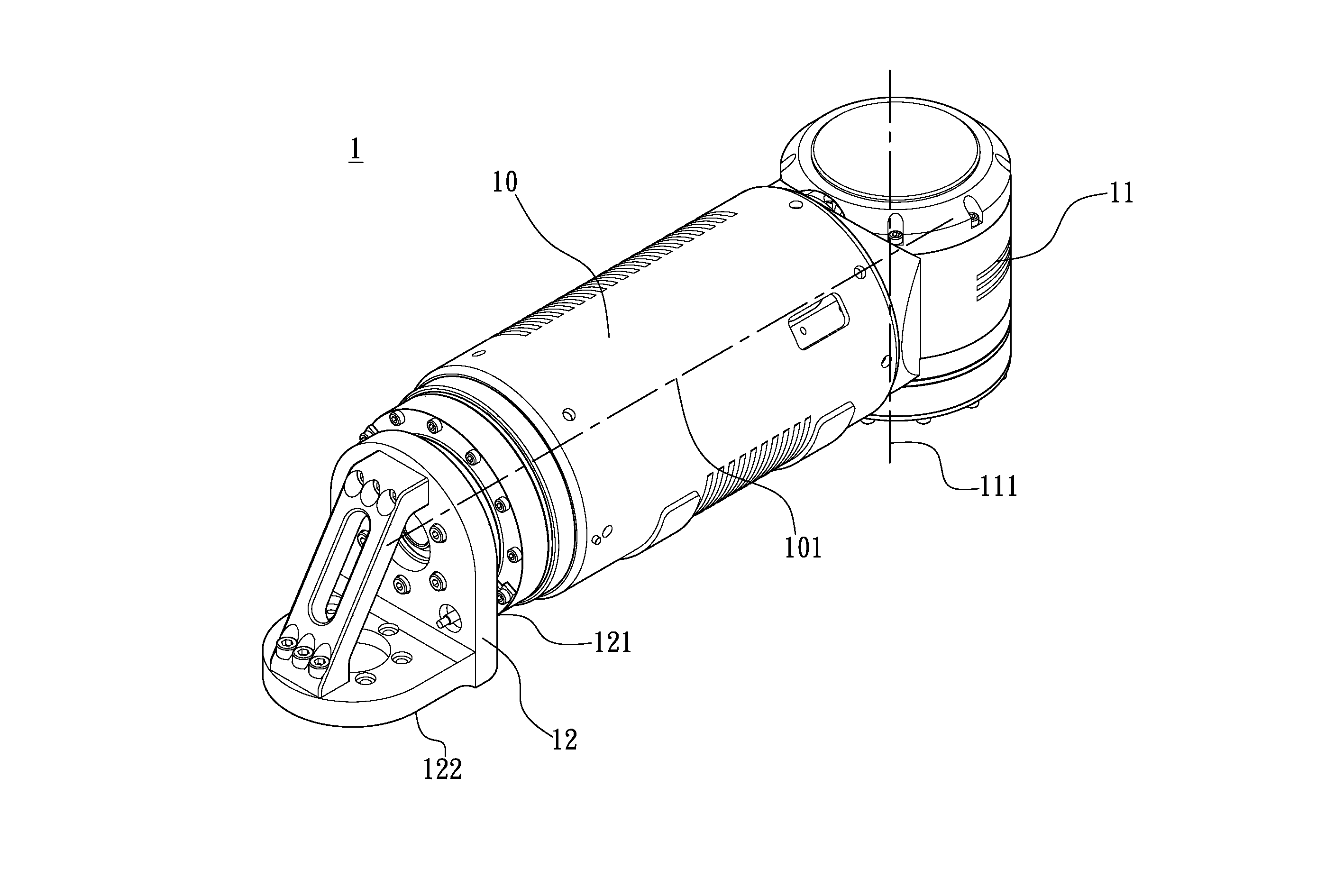
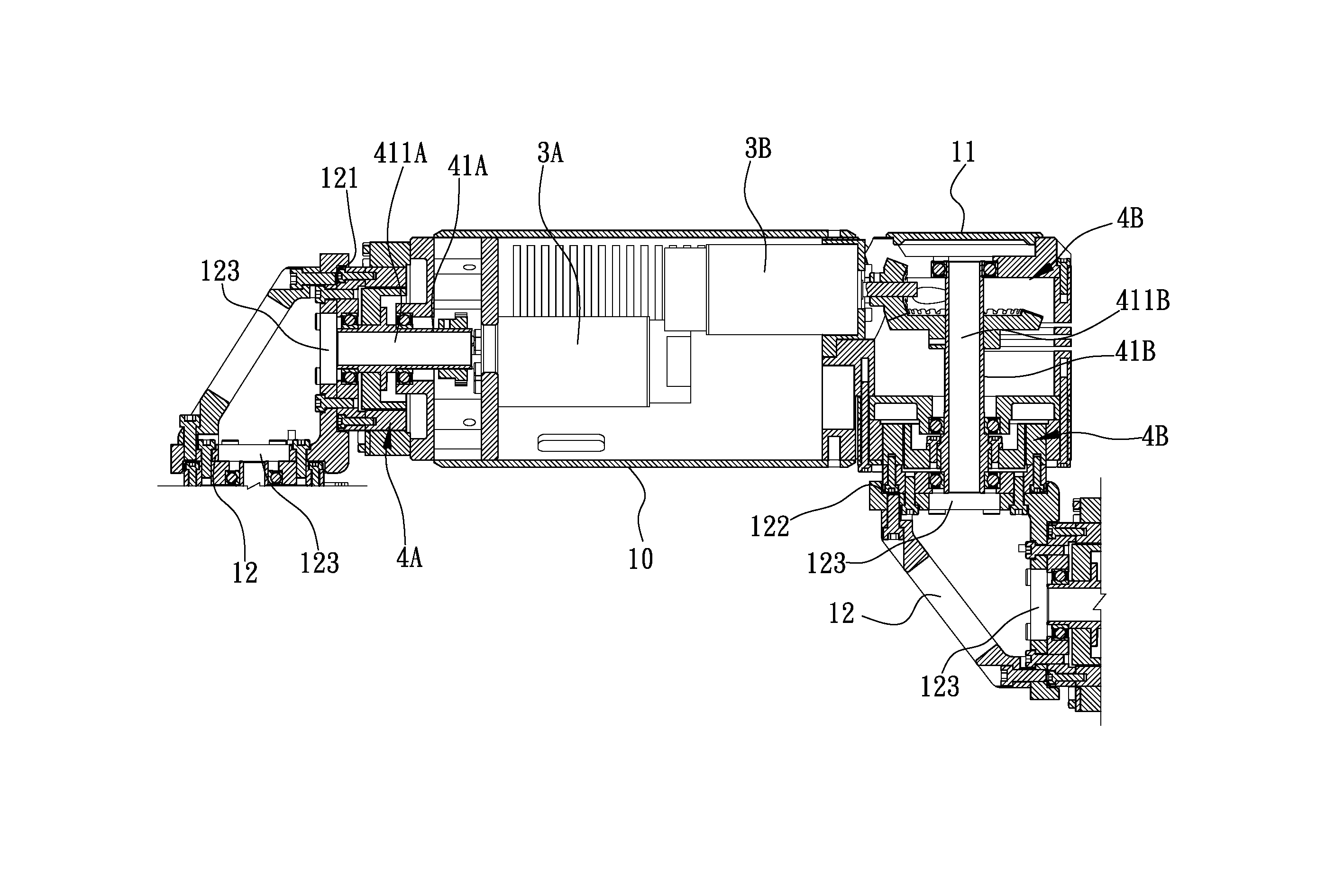
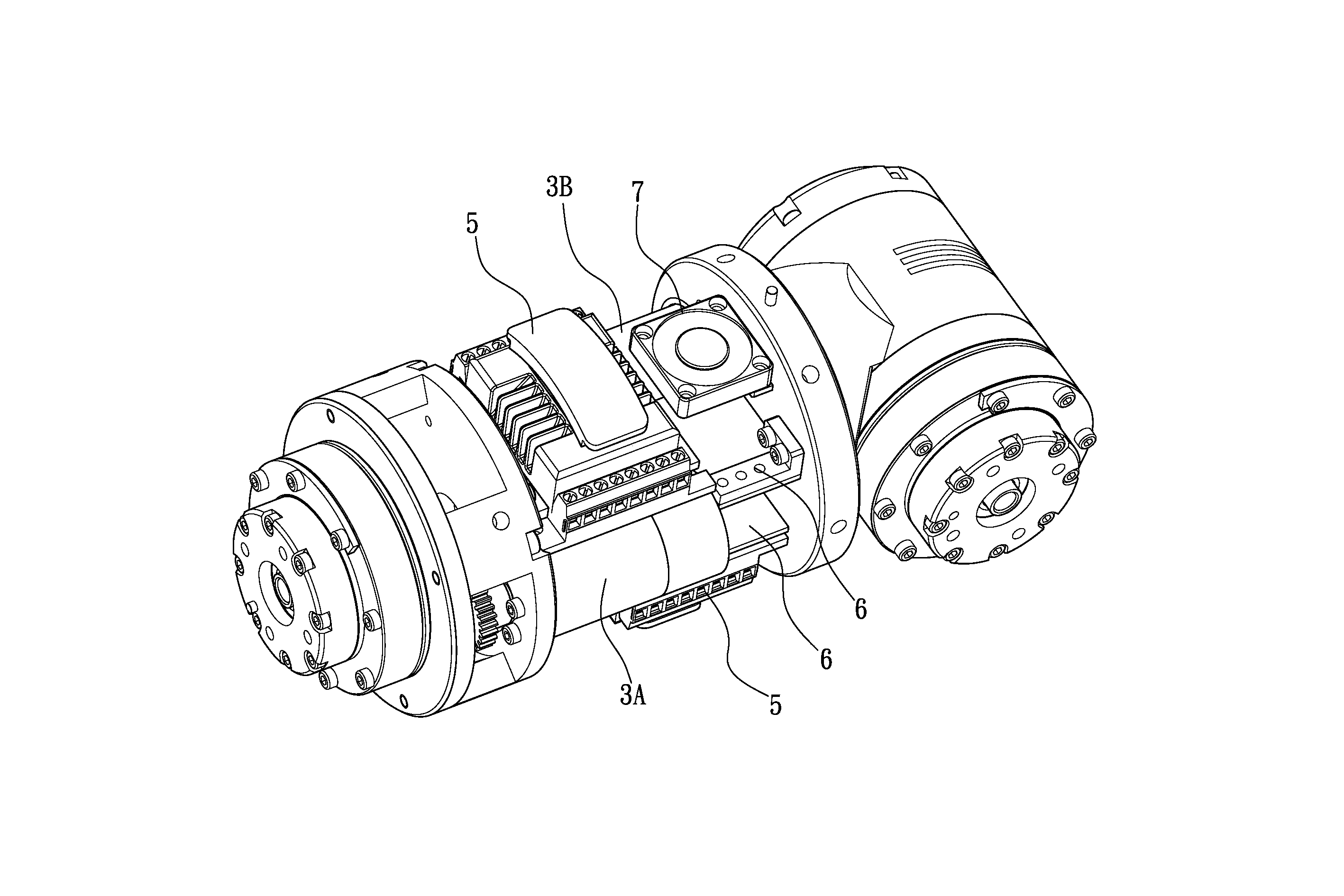
[0034] see Figure 1 to Figure 4 As shown, it is a preferred embodiment of the present invention, the multi-axis robot of the present invention is formed by a plurality of arm assemblies 1, as figure 1 As shown, the arm assembly 1 includes: a first arm portion 10, a second arm portion 11 and a connecting piece 12, one end of the first arm portion 10 and the second arm portion 11 are connected and fixed so that the first arm portion 10 There is no relative rotational freedom between the arm portion 10 and the second arm portion 11, and the axis lines 101, 111 of the first arm portion 10 and the second arm portion 11 are arranged at about 90 degrees to each other, and the connecting member 12 has a second The first connecting surface 121 and the second connecting surface 122, the connecting member 12 is in the s...


PUM


Abstract

The invention relates to a multi-axis robot. The multi-axis robot comprises a plurality of arm components, wherein the arm components comprise a first arm, a second arm and a connecting piece; one end of the first arm and one end of the second arm are mutually connected and fixed; the axial lead of the first arm and the axial lead of the second arm are mutually arranged in an approximate 90-degree mode; the connecting piece is provided with a first connecting surface and a second connecting surface, and the first connecting surface and the second connecting surface are arranged in an approximate 90-degree mode; the other end of the first arm is pivoted to the first connecting surface; the second connecting surface and the other end of the second arm of another arm component are mutually pivoted to form the multi-axis robot. The multi-axis robot can be stored in a relatively appropriate shape so as to achieve the requirements of reducing the size and facilitating the transportation.

Description

technical field [0001] The invention relates to a robot, in particular to a multi-axis robot. Background technique [0002] A multi-axis robot usually consists of several sequentially connected axis parts. Each shaft component includes a rotating shaft and a driving assembly for driving the rotating shaft to rotate. The rotating shaft of the end shaft part of the multi-axis robot can be equipped with end effectors such as fixtures, cutting tools and detectors to perform various actions. The drive assembly usually includes a motor and a reduction mechanism connected to the motor, such as a Harmonic Drive. For example, Japanese Patent Laid-Open No. 2000-271894 discloses a multi-axis robot, which is composed of joints with different rotational degrees of freedom to achieve the requirement of expanding the operating space. [0003] However, by the patent publication figure 1 It can be clearly seen that when the robot is in a stopped state, the arm of the robot needs to be su...

Claims


Application Information

Patent Timeline
Patent Type & Authority Applications(China)
IPC IPC(8): B25J9/04B25J18/00
Inventor 黄汉邦王仁政
Owner HIWIN TECH
Why Eureka
Try Eureka