An ice machine capable of exchanging the opening direction of the door body

An ice machine and door body technology, which is applied to ice making, ice manufacturing, door/window fittings, etc., can solve the problems of broken door body sealing state, damage, and unprotected ice cube hygiene, so as to avoid peculiar smells. , the effect of maintaining ventilation

Active Publication Date: 2016-08-24
青岛澳润商用设备有限公司
View PDF5 Cites 1 Cited by
  • Summary
  • Abstract
  • Description
  • Claims
  • Application Information

AI Technical Summary

Problems solved by technology

In the prior art, the door body of the ice machine is hinged on one side, and the other side is a free end, so that the door body can only be opened to one side, and the door opening direction is fixed, and due to the location of the ice machine If it is different, the original preset door opening direction of the ice machine cannot be opened, and the user needs to return to the factory for re-customization, which delays the normal use of the user and increases the user's cost of use, or the user directly modifies the door body, but the original door will inevitably be damaged during the modification process. The sealing state of the door affects the normal operation of the ice machine
[0003] In addition, due to the bumpy transportation environment of the traditional marine ice machine, accidental bumps and damages often occur when the door is opened.
Moreover, when the product is not in use for a long time, the closed door is likely to cause bacteria to grow on the ice maker and the door seal due to the special humid and airtight environment, which will affect the quality of ice making and make the produced ice cubes unsanitary. Assure
And the door lock in the prior art also does not have the function of adjusting the distance between the door body and the cabinet body, which brings a lot of inconvenience to the user

Method used


Image

  • An ice machine capable of exchanging the opening direction of the door body
  • An ice machine capable of exchanging the opening direction of the door body
  • An ice machine capable of exchanging the opening direction of the door body

Examples


Embodiment Construction

[0027] The present invention provides an ice maker capable of exchanging the opening direction of the door body. In order to make the purpose, technical solution and effect of the present invention clearer and clearer, the present invention will be further described in detail below. It should be understood that the specific embodiments described here are only used to explain the present invention, not to limit the present invention.

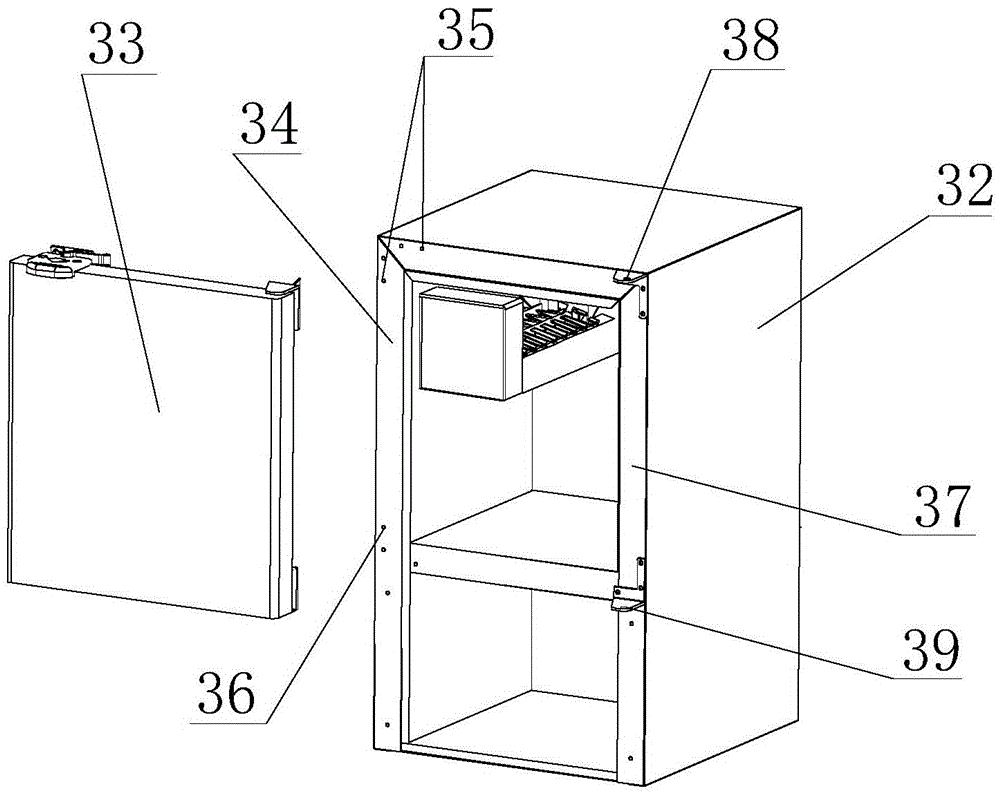
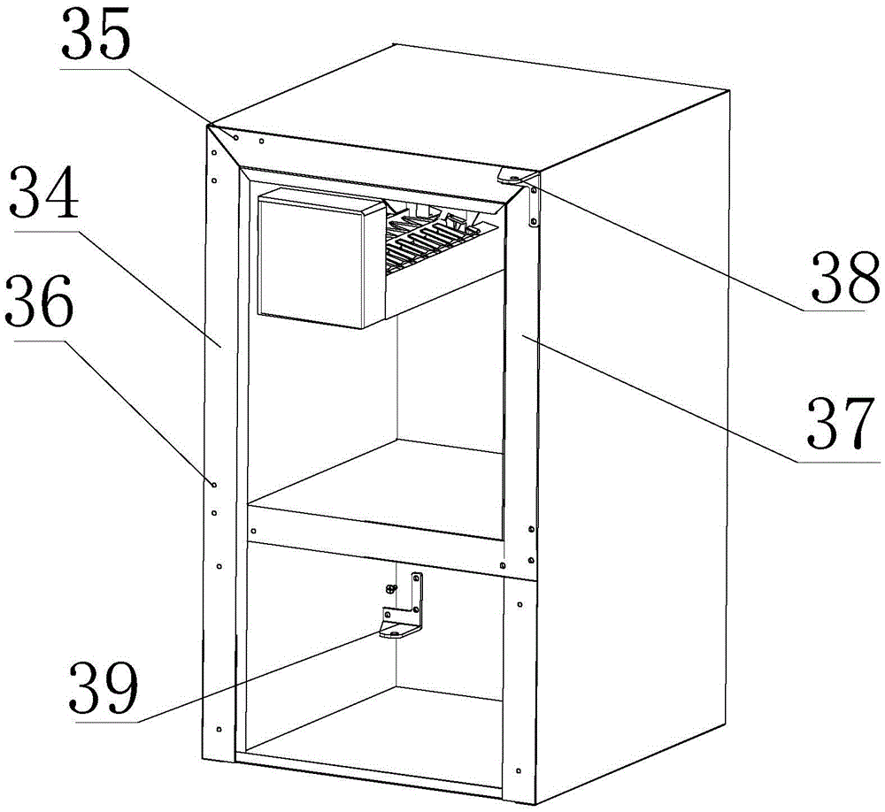
[0028] The invention provides an ice machine capable of exchanging the opening direction of the door body, such as figure 1 , figure 2 and image 3 As shown, it includes a cabinet body 32 and a door body 33, and the left side plate 34 of the cabinet body 32 is provided with an upper left mounting hole 35 and a lower left mounting hole 36, and the right side plate 37 is provided with an upper right mounting hole and a lower right mounting hole. hole (not shown in the figure because of the angle of view), the cabinet body 32 is equipped with an ...


PUM


Abstract

The invention discloses an ice machine capable of exchanging the opening direction of the door body. There are upper right mounting holes and lower right mounting holes, upper hinges and lower hinges are arranged on the cabinet body, and the upper hinges and lower hinges are mirror images of each other; left hinge holes are respectively set at the upper and lower ends of the left side of the door body, The upper and lower ends of the side are respectively provided with right hinge holes. The technical means of the upper hinge and the lower hinge that are mirror images of each other is adopted, and specific installation holes are preset on the cabinet body and the door body. When the user needs to open the door body to the corresponding side, the user can adjust the upper hinge and the lower hinge. The position on the door body and the cabinet body can be realized. It is not necessary to rotate the door body or change the state of the door body to realize the conversion of the opening direction of the door body, which is convenient for the user to install the position of the ice machine and switch the position of the door body according to the needs. Turn on directions.

Description

technical field [0001] The invention relates to an ice maker capable of realizing interchangeable opening directions of a door body. Background technique [0002] The ice machine is a device that uses water as a carrier to produce ice after passing through a certain device in the electrified state. According to the principle of the evaporator and the different production methods, the shape of the ice cubes generated is also different. Generally, according to the shape of the ice, ice machines are divided into granular ice machines, flake ice machines, plate ice machines, tube ice machines, shell ice machines, etc. . In the prior art, the door body of the ice machine is hinged on one side, and the other side is a free end, so that the door body can only be opened to one side, and the door opening direction is fixed, and due to the location of the ice machine If it is different, the original preset door opening direction of the ice machine cannot be opened, and the user need...

Claims


Application Information

Patent Timeline
Patent Type & Authority Patents(China)
IPC IPC(8): E06B3/36E05D7/02E05D5/06E05C19/12E05C17/02F25C1/00
Inventor 张进富彭丙艳徐涛刘丙伟
Owner 青岛澳润商用设备有限公司
Why Eureka
Try Eureka