
A Pseudo-incline Automatic Control System of Fully Mechanized Mining Face

An automatic control system and fully mechanized mining face technology, applied in mining equipment, earthwork drilling, tunnels, etc., can solve problems such as impact on the working face, extrusion, equipment slide, etc., and achieve high reliability, convenient use, and simple structure Effect

Active Publication Date: 2018-04-27
BEIJING TIANMA INTELLIGENT CONTROL TECH CO LTD
View PDF7 Cites 0 Cited by
  • Summary
  • Abstract
  • Description
  • Claims
  • Application Information

AI Technical Summary

Problems solved by technology

In the working face equipped with electro-hydraulic control system, due to the accumulation of sensor error and pin lug error in the control system, as well as the feedback delay of the hydraulic system, most of the equipment straightening operations in the fully mechanized mining face still use manual electronic control operation as the main means. The ups and downs of the equipment on the working face with a large inclination require operators to make specific judgments based on the site conditions and then perform manual control. In the prior art, the control of straightness is basically determined by the travel travel of the travel sensor. There is no set of calibration Once the travel sensor fails, the straightness of each hydraulic support and the scraper conveyor will have a large deviation, which will seriously affect the normal mining work of the working face
There is no relevant electronic control system solution and its supporting products when going up and down. If the equipment slides down seriously, it is easy to cause serious extrusion. Cause the transporter to push the reloader to the coal wall outside the transport lane, resulting in blockage of the safety exit at the end, and underground accidents.

Method used


Image

  • A Pseudo-incline Automatic Control System of Fully Mechanized Mining Face
  • A Pseudo-incline Automatic Control System of Fully Mechanized Mining Face
  • A Pseudo-incline Automatic Control System of Fully Mechanized Mining Face

Examples


Embodiment Construction

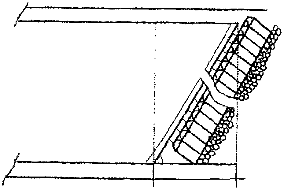
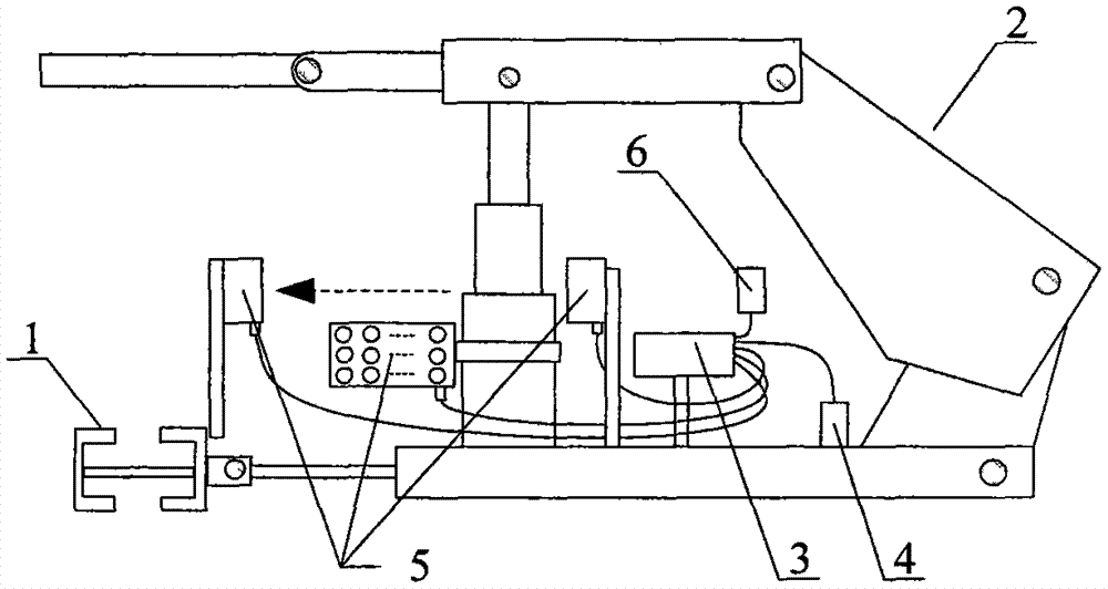
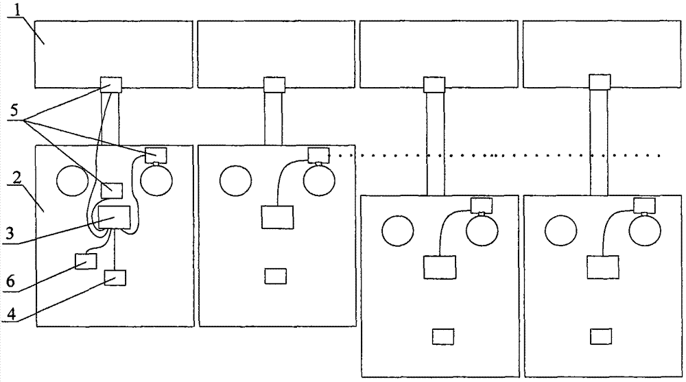
[0020] see Figure 1-3 , which describes a preferred embodiment of the pseudo-inclination automatic control system for the fully mechanized mining face according to the present invention. In this embodiment, the mining face is arranged obliquely along the strike, and the working face is arranged according to the pseudo-inclination control mode. It forms a parallelogram, and the scraper conveyor is controlled to move up and down through the pseudo-inclination of the working surface. As the working surface gradually advances, each hydraulic support pushes the front scraper conveyor forward in sequence. A support controller and a laser positioning sensor are installed on the hydraulic support. The support controller performs basic operations such as the movement of the support, and can communicate with other support controllers to send and receive data information. The support controller and the laser positioning sensor Through the connector connection, the support controller can...


PUM


Abstract

An automatic control system for a pseudo-inclined fully mechanized mining face comprises scrapper conveyers, hydraulic supports, support controllers, laser position sensors, laser range finders, angle sensors and inclination regulating jacks, each scrapper conveyer is formed by sequential connection of a plurality of chutes, every chute is connected with a pushing rod of the corresponding hydraulic support, the laser position sensors, the laser range finders and the angle sensors are connected with the support controllers via connectors, and one end of each inclination regulating jack is fixed on the adjacent hydraulic support in the gliding direction of the corresponding scrapper conveyer while the other end of the same is fixed on the chute connected with the local hydraulic support. The automatic control system for the pseudo-inclined fully mechanized mining face has the advantages that the problems of positioning and posture control of the hydraulic supports in the process of moving are solved via laser positioning signals, the vertical relation among the hydraulic supports and the scrapper conveyers are kept, component force, on the scrapper conveyers, generated by the hydraulic supports in the process of moving can be counteracted by weight components generated by the scrapper conveyers and the hydraulic supports, and thereby the problem of gliding up and down of workface equipment is solved.

Description

technical field [0001] The invention relates to an automatic control system for pseudo-inclination of a fully mechanized mining face, in particular to a method and a control system for solving the problems of straightening and upswing and downfalling of working face equipment on a working face with an inclination angle. Background technique [0002] The fully mechanized mining face is formed by multiple hydraulic supports arranged in sequence on the working face to support the roof of the working face and move the scraper conveyor. The hydraulic support of the working face is a floating system weakly constrained by the scraper conveyor. During the moving process of the working face, because the hydraulic support and the scraper conveyor are connected by pin lugs, there is a gap, which leads to certain errors in the moving process. In addition, due to the The accuracy of the stroke sensor that controls the movement of the hydraulic support is not high. The error caused by the...

Claims


Application Information

Patent Timeline
Patent Type & Authority Patents(China)
IPC IPC(8): E21D9/12
Inventor 牛剑峰李俊士刘清
Owner BEIJING TIANMA INTELLIGENT CONTROL TECH CO LTD
Features
  • Generate Ideas
  • Intellectual Property
  • Life Sciences
  • Materials
  • Tech Scout
  • Unparalleled Data Quality
  • Higher Quality Content
  • 60% Fewer Hallucinations
Learn More