A method for controlling gas drainage in goaf

A technology of gas extraction and control method, which is applied in gas discharge, mining equipment, earth-moving drilling, etc., can solve the problems of large consumption of pipes, increased cost, complicated installation, etc., and achieves low cost, convenient processing and low economic cost. Effect

Active Publication Date: 2016-05-11
TAIYUAN UNIV OF TECH
View PDF6 Cites 0 Cited by
  • Summary
  • Abstract
  • Description
  • Claims
  • Application Information

AI Technical Summary

Problems solved by technology

[0006] In order to solve the problems of large consumption of pipes, increased cost, cumbersome installation and easy damage in the existing goaf drainage technology, the present invention provides a gas drainage control method for goafs

Method used


Image

  • A method for controlling gas drainage in goaf
  • A method for controlling gas drainage in goaf
  • A method for controlling gas drainage in goaf

Examples


Embodiment Construction

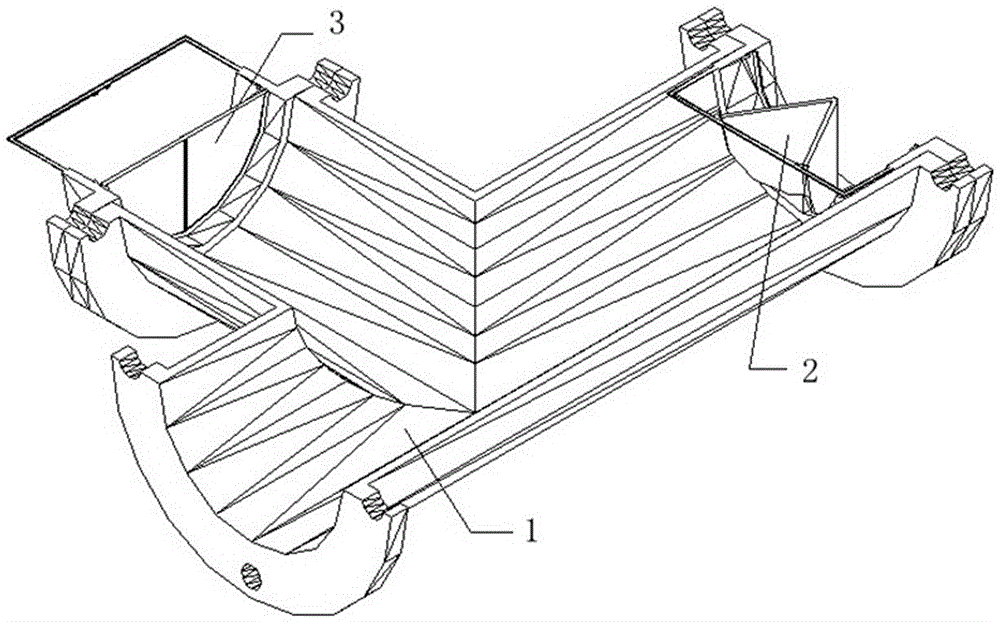
[0017] A gas drainage control device for a goaf, comprising a tee joint 1 connected at one end to the tail of a gas drainage main pipe, a main pipe switch 2 connected to the other end of the tee joint 1 opposite to the gas drainage pipe, and The third end of 1 is connected with branch switch 3;

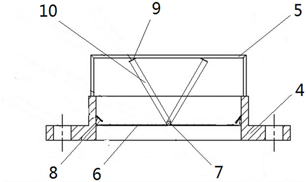
[0018] The dry pipe switch 2 includes a flange-shaped housing 4, an inverted U-shaped strut 5 is fixed on the protruding end of the housing 4, a rubber ring 6 is fixed on the cylindrical surface inside the housing 4, and the housing above the rubber ring 6 4. The inner side is fixed with a rotating shaft 7 and two non-return springs 8 with symmetrical positions. 8 and the semicircular rotating fan 10 that cooperates with the limit shrapnel 9;

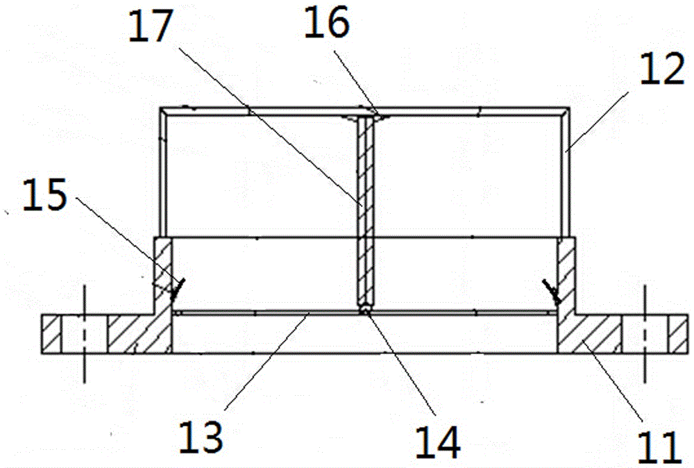
[0019] The branch pipe switch 3 includes a flange-shaped housing I11, an inverted U-shaped strut I12 is fixed on the protruding end of the housing I11, a rubber ring I13 is fixed on the cylindrical surface inside the housing I11, and the housi...


PUM


Abstract

The invention specifically provides a gob gas extraction device and method, and aims at solving the problems of large consumption on pipes, increase on cost, complex mounting, and easy damaging of the existing gob extraction technique. The gob gas extraction device comprises a tee joint; one end of the tee joint is connected with a main pipe switch and while the other end of the tee joint is connected with a branch pipe switch; the main pipe switch comprises a flange shaped housing; a reversed U-shaped supporting rod is fixed to the convex end of the housing; a rubber ring is fixed in the housing; a rotating shaft and a non-return spring sheet are fixed inside the housing; the limiting spring sheet is fixed to the U-shaped supporting rod; a rotating fan blade is hinged to the rotating shaft; the branch pipe switch comprises a flange shaped housing I; a reversed U-shaped supporting rod I is fixed to the convex end of the housing I; a rubber ring I is fixed in the housing I; a rotating shaft I and a limiting spring sheet I are fixed inside the housing I; a non-return spring sheet I is fixed to the U-shaped supporting rod I; a rotating fan blade I is hinged to the rotating shaft I. With the adoption of the gob gas extraction device and method, the control to the gas extraction in different gob areas is realized.

Description

technical field [0001] The invention relates to an underground gas drainage control technology in coal mines, in particular to a gas drainage control method in a goaf that is suitable for gas drainage in goafs where different areas need to be treated differently. Background technique [0002] Mine gas is an important threat to coal mine safety, and the gas from the goaf is an important source of gas in the mining face. [0003] At present, most mines use the method of gas extraction by buried pipes in the gob area of ​​the working face. It is to pre-install the main gas drainage pipe in the air return lane of the working face, and a series of branch pipes at a certain distance extend from the main pipe to the goaf. , through the negative pressure in the pipeline, the gas in the goaf is pumped into the main pipe through the branch pipe. [0004] According to the gas drainage effect of buried pipes, the goaf can be divided into three parts. The first part is within 0-30 meter...

Claims


Application Information

Patent Timeline
Patent Type & Authority Patents(China)
IPC IPC(8): E21F7/00
Inventor 邢玉忠王亮贾俊峰曹学军
Owner TAIYUAN UNIV OF TECH
Why Eureka
Try Eureka