Light source adjusting method and system

A light source adjustment and light source technology, applied in the direction of light source, electric light source, electroluminescent light source, etc., can solve the problems of high cost and long time, and achieve the effect of convenient testing

Inactive Publication Date: 2014-10-15
HONG FU JIN PRECISION IND (SHENZHEN) CO LTD +1
View PDF0 Cites 3 Cited by
  • Summary
  • Abstract
  • Description
  • Claims
  • Application Information

AI Technical Summary

Problems solved by technology

[0002] At present, when Automatic Optic Inspection (AOI) equipment is widely used in the industry to perform optical automatic inspection on the captured image of the object under test, the X-Y platform with high precision positioning is often used to fix the position of the object under test to ensure that the light source It is completely parallel to the measured object, but it takes a lot of time to fix the position of the measured object with a high-precision positioning X-Y platform, and the cost is relatively high

Method used


Image

  • Light source adjusting method and system
  • Light source adjusting method and system
  • Light source adjusting method and system

Examples


Embodiment Construction

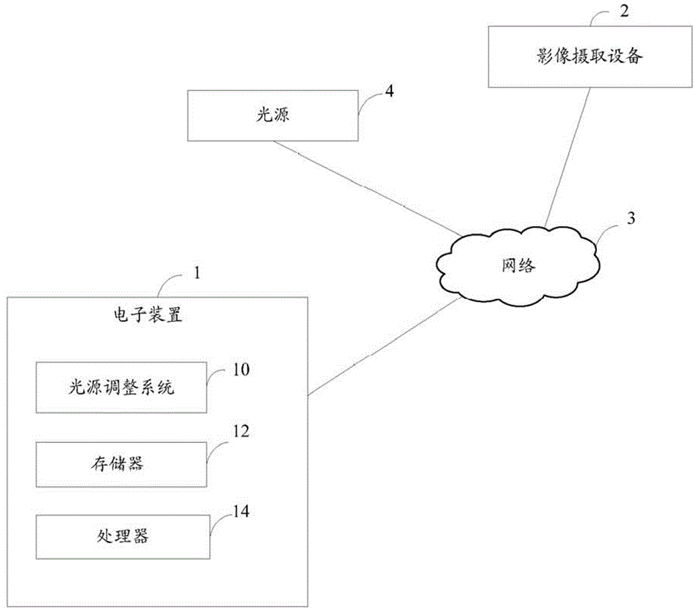
[0013] like figure 1 Shown is the operating environment diagram of the preferred embodiment of the light source adjustment system of the present invention. In this embodiment, the light source adjustment system 10 runs on an electronic device 1 , and the electronic device 1 is connected to the image capture device 2 and the light source 4 through the network 3 .

[0014] The electronic device 1 may be a computer, a smart phone, etc., and the electronic device 1 further includes a memory 12 and a processor 14 .

[0015] The image capture device 2 is used to capture a reference object (eg, a metal block) in real time when the reference object (eg, a metal block) moves cyclically in a certain order around the surface of the inspection table. The detection workbench is a platform on which objects to be measured are placed when automatic optical inspection (Automatic Optic Inspection, AOI) is performed.

[0016] The light source 4 can be an LED light source with an electric contr...


PUM


Abstract

The invention provides a light source adjusting method and a system. The system comprises an opening module, a shooting module, an acquiring module, a calculating module, a judging module, a first adjusting module, a counting module, and a second adjusting module, wherein the opening module is used for opening a light source irradiation detection work bench; the shooting module is used for controlling an image pickup apparatus to shoot a reference block in real time; the acquiring module is used for acquiring the image, which is shot in real time, of the reference block in each position around the detection work bench; the calculating module is used for calculating the average brightness of each image; the judging module is used for judging whether the average brightness of the acquired image is consistent; the first adjusting module is used for adjusting the light source to enable the average brightness of the image to be consistent; the counting module is used for counting the numbers of pixels distributed in a plurality of preset brightness areas in each image; and the second adjusting module is used for adjusting the light source to enable the numbers of the pixels in the plurality of brightness areas to be consistent if the numbers of the pixels in the plurality of brightness areas are not consistent. Through adjusting the light source, the numbers of pixels in the plurality of preset brightness areas of the reference object are consistent, the light sources can be adjusted to be fully parallel in relative to the testing platform, and convenience is provided for subsequent testing.

Description

technical field [0001] The invention relates to a light source adjustment method and system. Background technique [0002] At present, when Automatic Optic Inspection (AOI) equipment is widely used in the industry to perform optical automatic inspection on the captured image of the object under test, the X-Y platform with high precision positioning is often used to fix the position of the object under test to ensure that the light source It is completely parallel to the measured object, but using a high-precision positioning X-Y platform to fix the position of the measured object takes more time and is more expensive. Contents of the invention [0003] In view of the above, it is necessary to provide a light source adjustment method and system. [0004] The light source adjustment method includes: an opening step, turning on the light source to irradiate the detection workbench, and the detection workbench is a platform for placing the object to be tested when performing ...

Claims


Application Information

Patent Timeline
Patent Type & Authority Applications(China)
IPC IPC(8): H05B37/02H05B44/00
CPCH05B33/0854H05B45/10
Inventor 王光建
Owner HONG FU JIN PRECISION IND (SHENZHEN) CO LTD
Why Eureka
Try Eureka