Direct-current low-voltage power supply injection-locking power synthesis neon lamp
A technology of combining DC low-voltage power supply and injection-locking power, which is applied in the field of electric light source lighting, can solve the problems of shortening the service life, unstable power, accelerated aging of devices, etc., and achieves the effect of prolonging the service life, stabilizing the lighting, and avoiding power imbalance.
Active Publication Date: 2014-10-15
浙江振兴阿祥集团有限公司
View PDF2 Cites 1 Cited by
- Summary
- Abstract
- Description
- Claims
- Application Information
AI Technical Summary
Problems solved by technology
[0002] Electronic ballasts in the prior art usually use LC or RC oscillators as the neon light source, and the oscillation frequency generated is affected by the poor stability of temperature changes, and the power is unstable and the light intensity decreases. Especially, the neon lights powered by DC low-voltage power supply work at low voltage and high current. Although this electronic ballast has simple structure and low cost
Due to the low power supply voltage, it is necessary to increase the current to obtain high-power lighting, resulting in a sharp increase in the power consumption of the oscillating power tube and an excessive temperature rise, resulting in a change in the oscillating frequency, resulting in an imbalance in the power amplitude of the light as the frequency changes
At the same time, when the large current passes through the coil, the temperature rises and the magnetic permeability decreases, and the magnetic saturation inductance becomes smaller and the impedance tends to zero. The working time of the lamp is proportional to the temperature rise, and the temperature rise accelerates the aging of the device. Burning out components shortens service life
Method used
View moreImage
Smart ImageViewing Examples

Examples
Embodiment
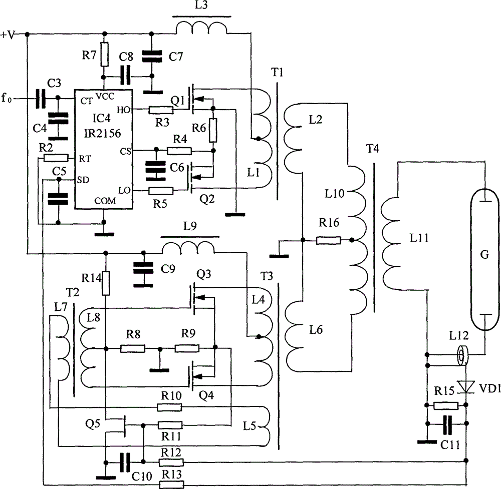
[0018] Example DC low-voltage power supply voltage 30V, inverter current 2.8A, igniting 70W neon tube G, efficiency 83%, day and night commercial decoration advertisement, power MOS tube temperature rise within the allowable value.
Login to View More PUM
 Abstract
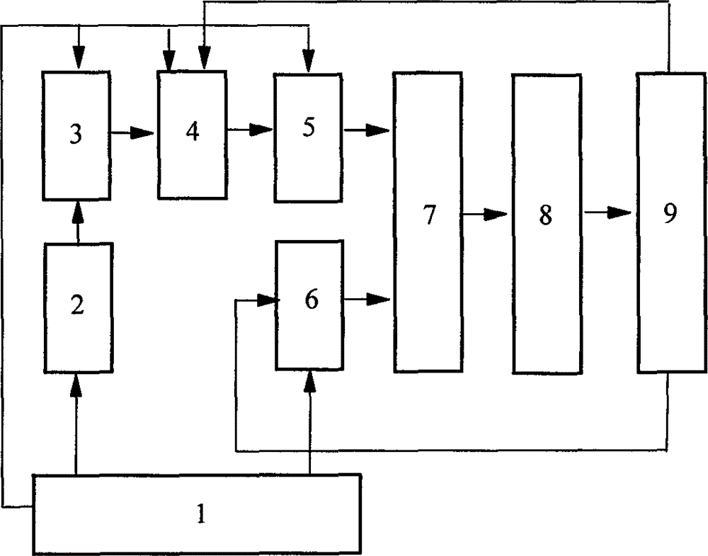
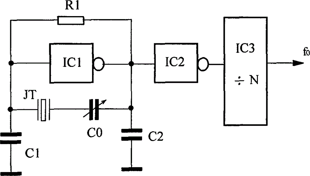
The invention relates to the technical field of electric light source illumination and specifically discloses a direct-current low-voltage power supply injection-locking power synthesis neon lamp. The neon lamp comprises a neon lamp tube, a direct-current low-voltage power supply, a reference crystal oscillator, an oscillation driving chip, a push-pull amplifier, a push-pull oscillator, an addition coupler and a lamp tube abnormal current detector. The output of the oscillation driving chip is connected to the push-pull amplifier. A power synthesis operation is performed on a transformer T1 and a push-pull oscillator transformer T3 through the addition coupler. The synthesized power further undergoes a voltage boost and is then accessed to the lamp tube for turning the lamp tube on. Signals of the reference crystal oscillator are injected into an RC oscillator of the oscillation driving chip through a frequency divider for phase locking. After power synthesis of the push-pull amplifier transformer T1 and the push-pull oscillator transformer T3, a cross-coupling injection-locking frequency pulls a coherent synchronous locking phase to achieve large-power illumination. Excessive temperature rise of the device, changes of oscillation frequency, imbalanced power and dim light are avoided. The neon lamp is suitably used in commercial decorative illumination occasions as a neon lamp powered by a direct-current low-voltage heavy-current power supply.
Description
technical field [0001] The invention relates to the technical field of electric light source lighting, in particular to a DC low-voltage power supply injection lock power synthesis neon lamp. Background technique [0002] Electronic ballasts in the prior art usually use LC or RC oscillators as the neon light source, and the oscillation frequency generated is affected by poor stability of temperature changes, and the power is unstable and the light intensity drops. Especially, neon lights powered by DC low-voltage power supply work at low voltage and high current. Although this electronic ballast has a simple structure and low cost. Due to the low power supply voltage, it is necessary to increase the current to obtain high-power lighting, resulting in a sharp increase in the power consumption of the oscillating power tube and an excessively high temperature rise, resulting in a change in the oscillation frequency. As a result, the power amplitude of the light will be unbalanc...
Claims
Login to View More Application Information
Patent Timeline
 IPC IPC(8): H05B41/285
CPCY02B20/00
Inventor 阮树成阮小青
Owner 浙江振兴阿祥集团有限公司