Cup box grabbing mechanism and cup box grabbing method

A technology for grabbing mechanisms and cup boxes, which is applied in the direction of conveyor objects, object destacking, transportation and packaging, etc. It can solve problems such as complex mechanical structures, overturning, and increased power consumption, and achieve reliable grabbing of cup boxes and maintenance. The effect of convenience and simple structure

Active Publication Date: 2014-10-22
SHENZHEN MINDRAY BIO MEDICAL ELECTRONICS CO LTD
View PDF5 Cites 15 Cited by
  • Summary
  • Abstract
  • Description
  • Claims
  • Application Information

AI Technical Summary

Problems solved by technology

The mechanical structure adopted by this conveying method is complicated. When replenishing the cup boxes, the tray needs to lift all the cup boxes on it up or down, which has great requirements on the stability of the cup boxes placed on the moving tray; if the tr

Method used


Image

  • Cup box grabbing mechanism and cup box grabbing method
  • Cup box grabbing mechanism and cup box grabbing method
  • Cup box grabbing mechanism and cup box grabbing method

Examples


Embodiment 1

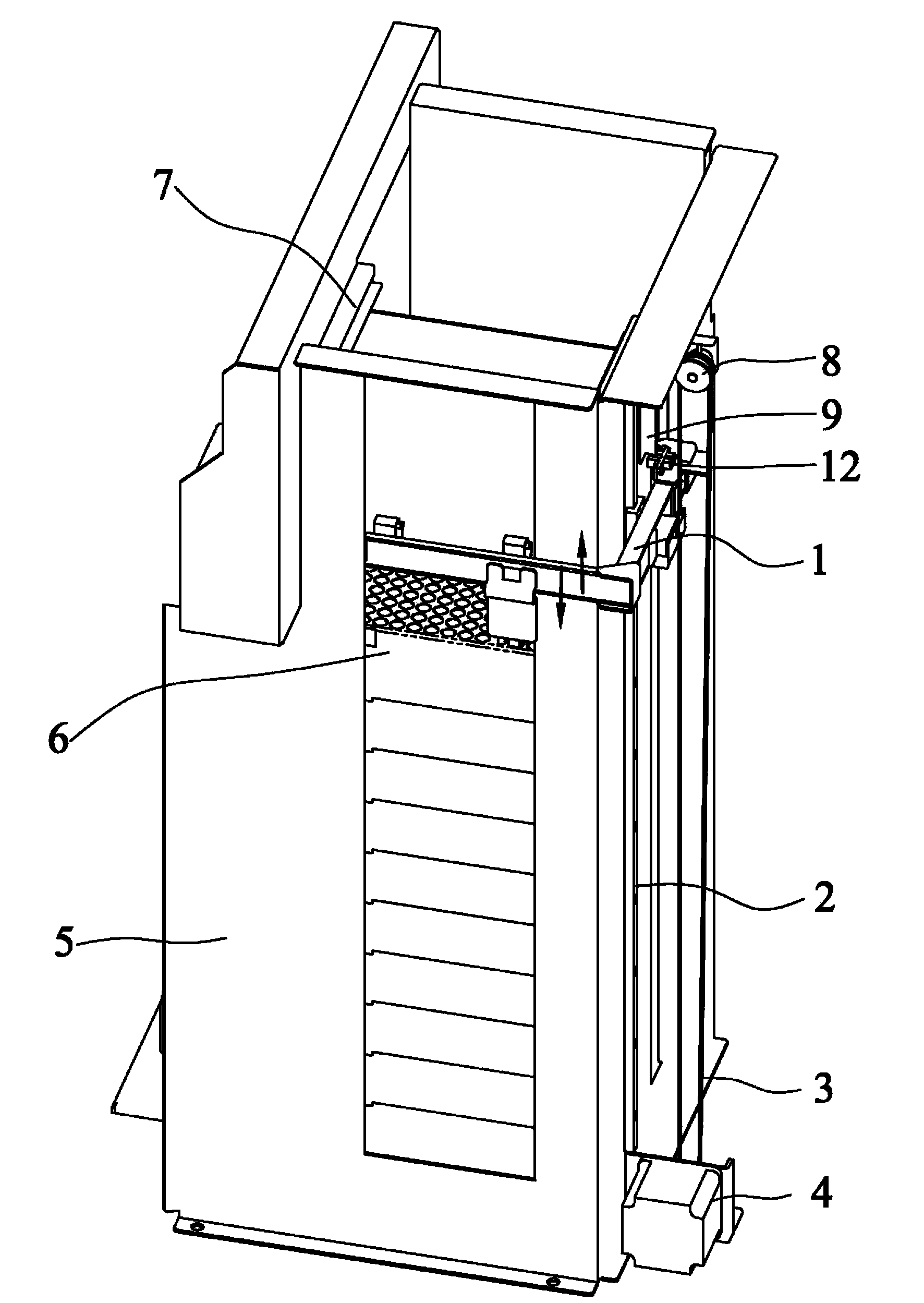
[0027] Such as figure 1 As shown, a cup box grabbing mechanism provided by the embodiment of the present invention includes a box body 5, a driving assembly and a grabbing assembly 1, and the driving assembly drives the grabbing assembly 1 to rise or fall vertically on the side of the box body 5. . A cup box 6 is stacked inside the box body 5 , and a code disc 9 is installed on the top of the box body 5 . The top of the code disc 9 is the waiting position 7 of the cup box 6 . The purpose of the cup box grabbing mechanism provided by the embodiment of the present invention is to enable the grabbing assembly 1 to grab a required number of cup boxes 6 from the cup box stacking area inside the box body 5, and transport and load them to the waiting position 7 superior.

[0028] Specifically, the drive assembly includes a motor 4 , a pulley 8 , a synchronous belt 3 connected between the motor 4 and the pulley 8 , a guide rail 2 extending in a vertical direction, and a slider insta...

Embodiment 2

[0037] The embodiment of the present invention also provides a method for grabbing a cup box using the cup box grabbing mechanism described in Embodiment 1, which needs to meet the following basic conditions:

[0038] First, the bottom width of each cup box 6 stacked in the box body 5 needs to be greater than the top width, and all cup boxes 6 need to be stacked;

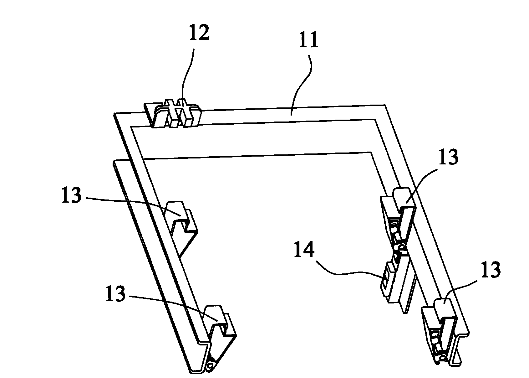
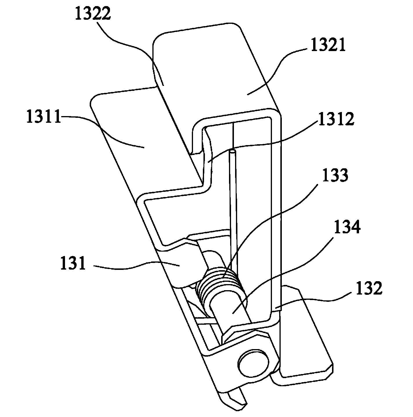
[0039] Secondly, when the rotating plate 131 on the finger 13 is at the maximum deflection stroke, the minimum distance L1 between the two fingers 13 is less than the width L2 of the cup box bottom; The minimum distance L3 between them is greater than or equal to the bottom width L2 of the cup box.

[0040] Described method specifically comprises the following steps:

[0041] S1. The grabbing assembly 1 descends vertically on the box body 5. When the reflective optocoupler 14 detects the cup box 6 at the highest place in the stacking area of ​​the cup box, grab the cup box 6 according to the required quantity and ...


PUM


Abstract

The invention discloses a cup box grabbing mechanism and a cup box grabbing method. The cup box grabbing mechanism comprises a box, a driving component and a grabbing component. The driving component drives the grabbing component to ascend or descend on the side face of the box along the vertical direction, and the grabbing component comprises an arm and fingers fixed on the arm. The cup box grabbing mechanism and the cup box grabbing method are used for realizing automatic conveying of cup boxes. The cup box grabbing method includes that one cup box is grabbed and separated to be conveyed to a specified position. The cup box grabbing mechanism adopts an arm structure, and the mechanical fingers are mounted on two sides of the arm; a reflection optocoupler is mounted on one side of the arm, the reflection optocoupler judges position of the cup box and gives out moving travel when the fingers move downwards, and a rotating plate after touching the edge of the cup box rotates around a shaft; when the fingers are lower than the bottom of the cup box, the rotating plate resets under action of a resetting spring to realize cup box grabbing. The cup box grabbing mechanism is simple in structure, reliable in cup box grabbing and convenient to maintain.

Description

technical field [0001] The invention relates to the field of medical equipment, in particular to a cup box grasping mechanism and method. Background technique [0002] During the operation of the automatic chemiluminescent immunoassay analyzer, it is necessary to manually add multiple stacked cup boxes to the conveying mechanism each time, and the transportation and replenishment of the reaction cup boxes are automatically completed by the mechanism. When the cup box at the working position is used up, the system executes the program instruction, firstly recovers the empty cup box at the working position to the blanking area for stacking, then transports the cup box at the waiting position to the working position and clamps it for positioning, finally Convey a cup box replenishment from the feeding area to the waiting position. When the cup boxes in the loading area are used up or the waste and empty cup boxes in the unloading area are stacked to the maximum, the system wil...

Claims


Application Information

Patent Timeline
IPC IPC(8): B65G47/90B65G59/02
Inventor 刘军华黄挺
Owner SHENZHEN MINDRAY BIO MEDICAL ELECTRONICS CO LTD
Why Eureka
Try Eureka