Mine downhole drilling well logging analysis meter and method

An analyzer and logging technology, applied in wellbore/well components, measurement, earthwork drilling, etc., can solve problems such as large quality impact, hole inclination, and deviation between drilling trajectory and design, and achieve accurate and low-cost results. Power consumption, meet the effect of small size

Active Publication Date: 2014-10-22
西安瑞泰电气有限公司
View PDF5 Cites 35 Cited by
  • Summary
  • Abstract
  • Description
  • Claims
  • Application Information

AI Technical Summary

Problems solved by technology

However, there are obvious deficiencies in the identification of rock formation lithology: (1) It is greatly affected by the recognition ability of human eyes and the quality of drilling construction (borehole wall smoothness, rock formation softness and hardness, etc.), and it cannot be well distinguished only by photos or videos Similar lithology, such as siltstone, mudstone
(2) Limited by shooting conditions (such as shooting angle, light, drilling medium, and muddy water in the drilling), the interpretation of videos or photos will vary greatly
Due to the above limitations, it is unreliable to conduct lithology identification and stratification of downhole boreholes only based on video camera technology
[0004] Significant hole inclination often occurs in downhole drilling. Whether on the plane or in the profile, the drilling trajectory and design will deviate, especially when the design inclination is relatively small, it will be very obvious, which will lead to drilling design The goal cannot be achieved, and the geological phenomenon cannot be explained when the hole inclination is serious

Method used


Image

  • Mine downhole drilling well logging analysis meter and method
  • Mine downhole drilling well logging analysis meter and method

Examples


Embodiment Construction

[0038] The present invention will be described in further detail below in conjunction with the accompanying drawings.

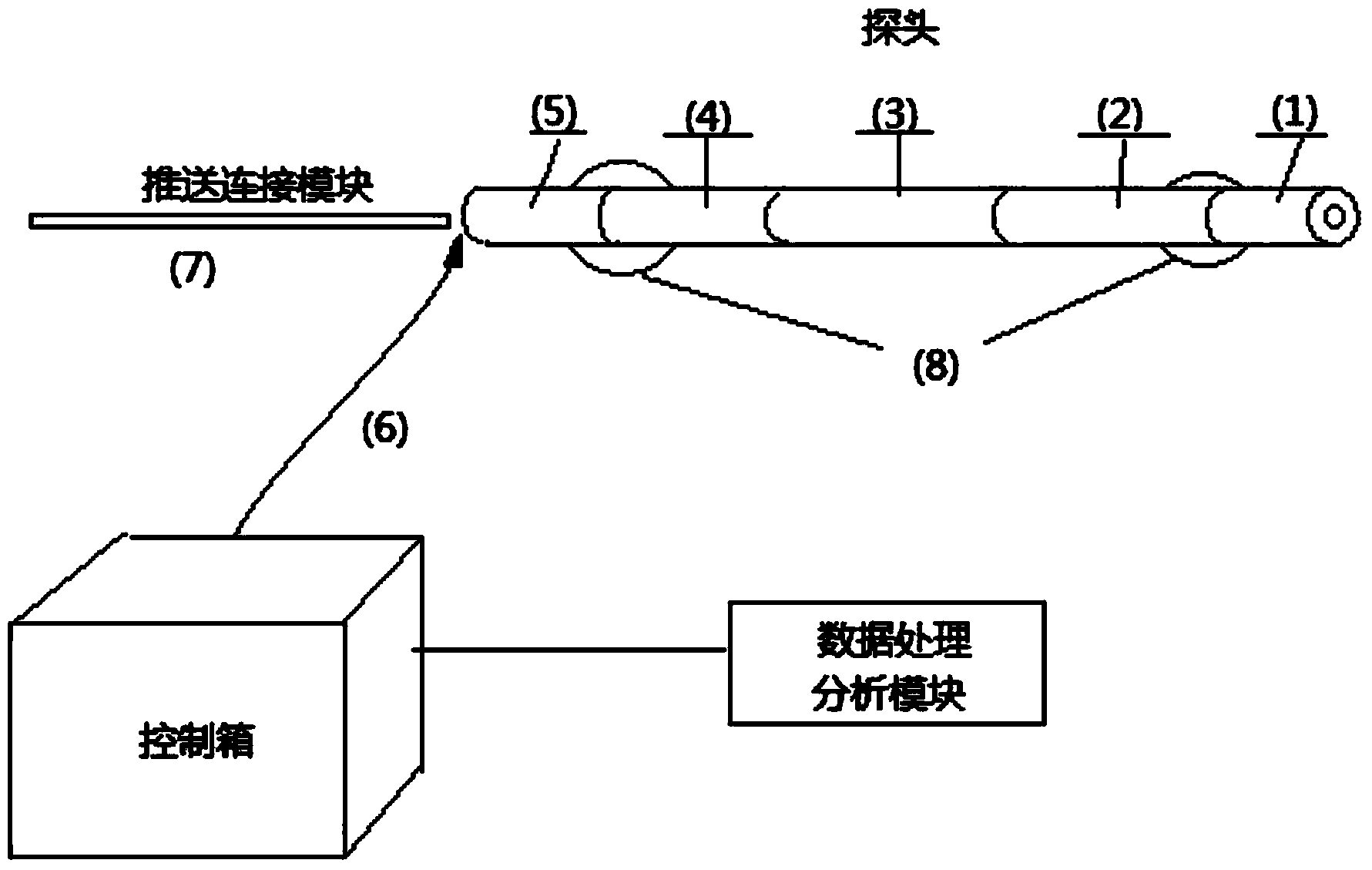
[0039] see figure 1 , a mine borehole logging analyzer, including a probe, a push rod 7, a connecting cable 6 and a control box.

[0040] Wherein, the probe includes a metal casing and a transmission and control unit 4, a hole inclination measurement unit 3, a natural gamma unit 2 and a camera unit 1 which are arranged in the metal casing and are sequentially connected; the natural gamma unit 2 and the hole inclination measurement unit 3 respectively The collected data is sent to the transmission and control unit 4 for conditioning, and the data after conditioning is stored by the transmission and control unit 4 or sent to the control circuit unit in the control box for storage and / or display; the image collected by the camera unit 1 The data is sent to the control circuit unit in the control box through the connecting cable 6 or transmitted to the control c...


PUM


Abstract

The invention discloses a mine downhole drilling well logging analysis meter and method. The analysis meter comprises a probe, a pushing rod, a connecting cable and a control box, wherein the control box comprises a box body, a display unit, a data storage unit, a control circuit unit, a power source unit and a depth metering module, the display unit, the data storage unit, the control circuit unit, the power source unit and the depth metering module are arranged inside the box body, the probe comprises a metal shell, a transmission and control unit, a hole deviation measuring unit, a natural gamma unit and a camera unit and / or a power supply unit, and the transmission and control unit, the hole deviation measuring unit, the natural gamma unit and the camera unit and / or the power supply unit are sequentially connected inside the metal shell. The method comprises the steps of (1) drilling designated section locus calculation, (2) drilling plane locus calculation, (3) rock stratum lithology layering and (4) drilling structure and water yield property analysis. According to the mine downhole drilling well logging analysis meter and method, detection of layering lithology, rock stratum hardness degree, blowholes, fractures, water points and roof separation situation is carried out on various drilled holes under a well, the true rock stratum thickness, the drilling section locus and the drilling plane locus are calculated, and then a drilling predicted geological section map can be drawn.

Description

【Technical field】 [0001] The invention belongs to the technical field of borehole detection and logging, and relates to an underground borehole logging analyzer and method in mines. 【Background technique】 [0002] At present, in geological exploration, the conventional method of drilling formation and lithology is mainly to use geophysical well detection, which has become the industry standard. A variety of logging methods (such as natural gamma ray, spontaneous potential, density, apparent resistivity, double-receipt time difference, borehole diameter, etc.) are often used for detection, and it is usually stipulated that more than four parameters are required to accurately judge the formation lithology. However, for the lithology detection of boreholes in the underground environment of mines (such as anchor cable holes, the diameter is only 28mm, 31mm), due to the limitation of current technical conditions, the design size of most logging instruments cannot be designed to b...

Claims


Application Information

Patent Timeline
Patent Type & Authority Applications(China)
IPC IPC(8): E21B49/00E21B47/002E21B47/022E21B47/04E21B47/00
Inventor 马庆勋
Owner 西安瑞泰电气有限公司
Why Eureka
Try Eureka