Slowly-open slowly-close fully-open and vibration-free swing check valve

A swing-type, check valve technology, applied in the direction of valve details, control valves, valve devices, etc., can solve the problems of increased water loss in the system, wear of the valve shaft system, fatigue damage of the valve shaft, etc., and achieve small vibration of the valve disc , Reduce system water loss and save energy

Active Publication Date: 2014-10-22
WUHAN SHENGYU DRAINING SYST
View PDF5 Cites 0 Cited by
  • Summary
  • Abstract
  • Description
  • Claims
  • Application Information

AI Technical Summary

Problems solved by technology

The electric slow-closing swing check valve needs to be associated with the water pump due to power-on and power-off. Once a non-accidental power failure occurs, the valve cannot automatically check and loses the role of the protection system.
[0003] The hydraulic slow-closing swing check valve has the following disadvantages: it does not have the function of closing the valve to start, and it is generally required to close the valve to start when the centrifugal pump is working. The existing hydraulic swing slow-closing check valve does not have This function requires manual adjustment of the external pressure of the slow closing device to meet the pressure requirements of the slow closing device when the system pressure changes, that is, when the system pressure increases, the relative external pressure increases

Method used


Image

  • Slowly-open slowly-close fully-open and vibration-free swing check valve
  • Slowly-open slowly-close fully-open and vibration-free swing check valve
  • Slowly-open slowly-close fully-open and vibration-free swing check valve

Examples


Example Embodiment

[0022] The present invention will be further described in detail below with reference to the drawings and specific embodiments to facilitate a clear understanding of the present invention, but they do not limit the present invention.

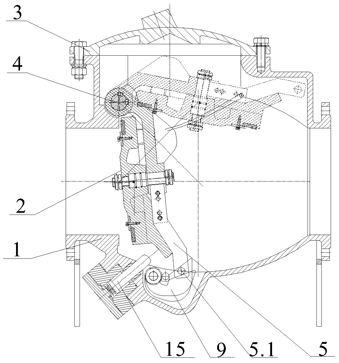
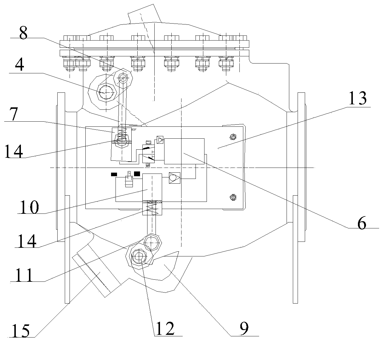
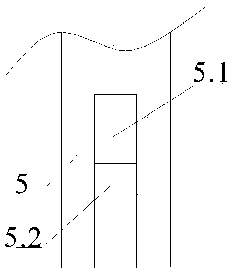
[0023] Such as figure 1 , figure 2 As shown, the present invention includes a valve body 1, a valve cover 3 arranged on the valve body 1, a valve shaft 4 arranged at the upper end of the valve body 1 near the end of the water inlet, and a valve disc 2 fixedly connected to the valve shaft 4. The valve shaft 4 passes through the valve body to extend out of the valve body 1, and a locking arm 5 is fixed on the inner side of the valve disc 2 to combine image 3 As shown, the end of the locking arm 5 is provided with a groove 5.1, and a locking shaft 5.2 for hooking with the locking hook 9 is connected in the groove 5.1, and the valve shaft 4 extends out of the valve body 1 One end of the valve shaft crank 8 is fixedly connected, the other end of the va...


PUM


Abstract

The invention relates to a slowly-open slowly-close fully-open and vibration-free swing check valve, and belongs to the technical field of valves. The swing check valve comprises a valve body, a valve deck arranged on the valve body, a valve shaft arranged at the upper end, close to a water inlet, inside the valve body, and a valve clack fixedly connected to the valve shaft. The valve shaft penetrates through the valve body and stretches out of the valve body, a locking arm is fixed to the inner side of the valve clack, and the part, stretching out of the valve body, of the valve shaft is connected with a first driving device; the valve body is provided with a rotating shaft, the part, located in the valve body, of the rotating shaft is fixedly connected with a locking hook used for hooking the locking arm, and the part, stretching out of the valve body, of the rotating shaft is connected with a second driving device. The swing check valve plays a role in sealing and checking, and also has a locking function. The swing check valve has valve closing and opening functions, when a system operates normally, a valve closure member, namely the valve clack, can be fully opened, water damage of the system is reduced, energy resources are saved, and shaking of the valve clack is small after the valve is opened.

Description

technical field [0001] The invention belongs to the technical field of valves, in particular to a slow-opening and slow-closing full-opening vibration-free swing check valve. Background technique [0002] At present, the existing swing check valves with slow closing (two-stage valve closing) capability are generally divided into three categories: pneumatic type, hydraulic type and electric type. Pneumatic slow-closing swing check valves require special air sources and DC equipment, so the application occasions are too limited. The electric slow-closing swing check valve needs to be associated with the water pump due to power-on and power-off. Once a non-accidental power failure occurs, the valve cannot automatically check and loses the function of the protection system. [0003] The hydraulic slow-closing swing check valve has the following disadvantages: it does not have the function of closing the valve to start, and it is generally required to close the valve to start wh...

Claims


Application Information

Patent Timeline
IPC IPC(8): F16K15/03F16K15/18F16K31/52F16K31/122
CPCF16K15/03F16K35/00F16K47/00F16K15/1821
Inventor 周超
Owner WUHAN SHENGYU DRAINING SYST
Why Eureka
Try Eureka