Double-layer stripping mechanism of ironware drawing die

A drawing die, double-layer technology, applied in the field of metal drawing die double-layer stripping mechanism, can solve the problems of reducing production volume, increasing the difficulty of mold adjustment, affecting production speed, etc., to reduce the cost of mold repair and stamping production cost , Guarantee the appearance quality and reduce the effect of mold repair time

Active Publication Date: 2014-10-29
TIANJIN DEV ZONE JINGRUI PRECISION MOLD
View PDF8 Cites 1 Cited by
  • Summary
  • Abstract
  • Description
  • Claims
  • Application Information

AI Technical Summary

Problems solved by technology

[0004] Existing problems: 1. The traditional drawing die stripping structure is not suitable for stretched products with high flanges, high appearance requirements, strict size requirements, and complex shapes. , Positioning is difficult, positioning is not accurate, resulting in product deformation, difficulty in stripping, the higher the stretched product, the higher the internal positioning. In the stamping process, it is not very convenient to place the product, and the speed is slow, and it is easy to place the product. After the stretching is completed, it is not easy to take out the stretched product because the stretched product is too high, which affects the production speed. The stretched product is prone to stretch marks, spots, crushing, and even the stretched product will have obvious double Eyelids, local parts will have bad phenomena such as bulging, material accumulation, and less material, which will increase the difficulty of mold repair, reduce production volume, increase product defect rate and production costs, material costs, and fail to meet customer quality Require
2. With the traditional stretching stripping mechanism, the stripping forces in the two directions of the upper mold inner stripping and the lower mold outer stripping are all concentrated on the product, which plays the role of pressing and stripping. Both the upper and lower molds are The product is ejected with a spring, so that the product is easily deformed, and the flatness cannot meet the requirements, which increases the difficulty of subsequent mold adjustment

Method used


Image

  • Double-layer stripping mechanism of ironware drawing die
  • Double-layer stripping mechanism of ironware drawing die
  • Double-layer stripping mechanism of ironware drawing die

Examples


Embodiment Construction

[0017] The technical solutions in the embodiments of the present invention will be clearly and completely described below in conjunction with the embodiments of the present invention. Apparently, the described embodiments are only some of the embodiments of the present invention, not all of them. Based on the embodiments of the present invention, all other embodiments obtained by persons of ordinary skill in the art without making creative efforts belong to the protection scope of the present invention.

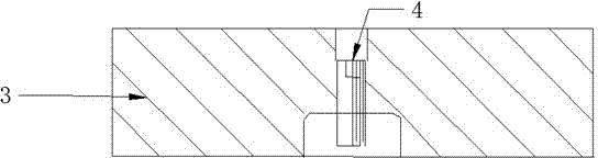
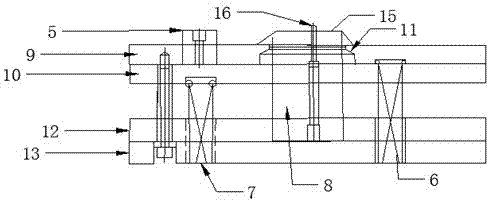
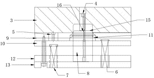
[0018] see Figure 1-Figure 6 , in an embodiment of the present invention, a double-layer stripping mechanism for a metal drawing die includes an upper mold assembly and a lower mold assembly, the upper mold assembly includes a mold sleeve 3 and an inner stripping block 4 of the mold sleeve, and the lower mold assembly Including inner limit column 5, lower stripping plate I spring 6, lower stripping plate II spring 7, male punch 8, lower stripping plate I9, lower stripping pl...


PUM


Abstract

The invention discloses a double-layer stripping mechanism of an ironware drawing die. The double-layer stripping mechanism comprises an upper die assembly and a lower die assembly, the upper die assembly comprises a die sleeve and a stripping block in the die sleeve, the lower die assembly comprises an inner limiting column, a lower stripping plate I spring, a lower stripping plate II spring, a male punch, a lower stripping plate I, a lower stripping plate II, an inner stripping block in the lower stripping plate, a lower clamping plate, a lower backing plate and a lower die base. The double-layer stripping mechanism is easy to position, stripping is smooth, the lower stripping plate I takes charge of material pressing, and the lower stripping plate II takes charge of stripping. The appearance quality of drawn products is ensured, dimensional stability of the products is ensured, the die repairing time is shortened, die repairing cost is reduced, and the production yield is increased.

Description

technical field [0001] The invention relates to the field of molds, in particular to a double-layer stripping mechanism for a metal drawing mold. Background technique [0002] At present, the drawing dies used by most mold companies are all traditional drawing die stripping structures, that is, upper die components: upper die base, upper backing plate, master template, inner stripping plate, and lower die components: lower Die male punch, outer stripping plate, lower splint, lower backing plate, and lower mold base; the upper and lower molds are stripped through the upper mold internal stripping and the lower mold external stripping to complete the pressing and stripping action. Its structure is simple and low in cost. Simple, uncomplicated and in cases where the flange stretch is not high, it can be used. [0003] As customers have more and more stringent requirements for appearance products, it is required that the products must ensure good appearance quality and sta...

Claims


Application Information

Patent Timeline
Patent Type & Authority Applications(China)
IPC IPC(8): B21D37/10B21D45/08
Inventor 张爱民李威
Owner TIANJIN DEV ZONE JINGRUI PRECISION MOLD
Why Eureka
Try Eureka