Method for controlling roll gap of pinch roll

A control method and technology of pinch rollers, which are applied in manufacturing tools, metal processing equipment, feeding devices, etc., can solve the problem that the belt threading head cannot be pinch normally, the gap between the pinch rollers is irregular, and the surface characteristics are very different. It can reduce the damage of the lead strip, strengthen the automatic adaptation, and improve the antegrade rate.

Active Publication Date: 2014-10-29
BAOSHAN IRON & STEEL CO LTD
View PDF5 Cites 6 Cited by
  • Summary
  • Abstract
  • Description
  • Claims
  • Application Information

AI Technical Summary

Problems solved by technology

[0008] There are two key defects in the existing control method: First, the accuracy control is not accurate: the main performance is that the setting of the pinch roller gap is irregular and can be checked, which is an empirical value, and the operator often manually adjusts the pinch roller gap set value
The second is that the expansion is not strong and the adaptability is poor: the main performance is that the setting value of the pinch roller gap is determined according to the thickness specification of the strip. When the material properties of the strip change, especially for electrical steel products, the silicon content from 0.10% to 3.5% fluctuation, the strength and surface properties of materials with different silicon content are very different. If you still use the pinch roller gap setting value corresponding to the thickness of the specification, it will cause the belt head to fail to pinch and wear normally. There are many defects in the strip head, and the strip yield is low

Method used


Image

  • Method for controlling roll gap of pinch roll
  • Method for controlling roll gap of pinch roll
  • Method for controlling roll gap of pinch roll

Examples


Embodiment Construction

[0047] The present invention will be described in detail below in conjunction with the accompanying drawings.

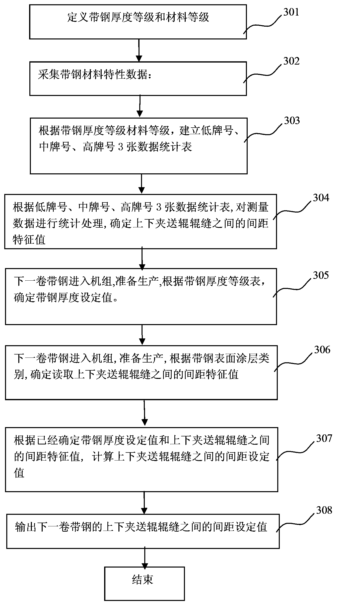
[0048] image 3 It is a flow chart of the pinch roll gap control method of the present invention.

[0049] As shown in the figure, step 301 is to divide the steel strip thickness grade and the silicon content grade of the material; the strip steel produced is divided into 5 strip steel thickness grades according to the thickness, and the strip steel is divided into low grade, high grade, high grade steel strip according to the silicon content of the material. There are three grades of silicon content in materials of medium grade and high grade. As shown in Table 2 and Table 3, the strip thickness grade table and material silicon content grade table.

[0050]Table 2: Strip Thickness Grade Table

[0051] Strip Thickness (mm)

Strip Thickness Grade

Strip thickness setting value T(mm)

0.10≤H<0.18

1

0.15-0.19

0.18≤H<0.30

2

...


PUM


Abstract

The invention discloses a method for controlling a roll gap of a pinch roll. The method includes the steps of (1) grading strip steel thicknesses and material silicon content; (2) collecting strip steel material characteristic data; (3) respectively building low-grade, medium-grade and high-grade material silicon content data statistical tables, and obtaining historical actual performance values and historical set values, corresponding to the strip steel thickness grades and the material silicon content grades, of the roll gap between an upper clamping roll body and a lower clamping roll body; (4) enabling strip steel to enter a unit, and determining the strip steel thickness set value T according to the strip steel thickness grades; (5) determining a gap control coefficient K of the strip steel according to the material silicon content grade data statistical tables; (6) calculating the finial set value G of the roll gap between the upper clamping roll body and the lower clamping roll body, wherein the G is the product of the T and the K and is the finial set value of the roll gap of the clamping roll, and the T is the strip steel thickness set value. The method is accurate in accuracy control and high in expansibility and adaptability, a steel strip head can be normally clamped and conveyed and can normally penetrate through the clamping roll, defects are avoided, and the strip steel yield is high.

Description

technical field [0001] The invention relates to a method for controlling the roll gap of pinch rolls, in particular to a method for controlling the roll gap of pinch rolls used in conjunction with disc shears in a finishing unit for producing electrical steel products. Background technique [0002] The disc shears of the finishing unit are important equipment to ensure that the edge of the strip is cut neatly, and the pinch rollers that match it behind the disc shears are one of the key equipment that determines whether the disc shears can start shearing smoothly. [0003] figure 1 is a schematic diagram of the edge of strip sheared by disc shearing. In order to ensure that the disc shears can start to cut the strip smoothly, generally a pinch roller should be placed behind the disc shears to clamp the head of the strip and send it to the coiler or tensioning / braking device smoothly. and build some tension. The force of the pinch rollers to pinch the strip should not be t...

Claims


Application Information

Patent Timeline
Patent Type & Authority Applications(China)
IPC IPC(8): B21D43/09
Inventor 赵河山朱华杨光王维
Owner BAOSHAN IRON & STEEL CO LTD
Why Eureka
Try Eureka