Assembling device of piston ring

An assembly device and piston ring technology, applied in metal processing, metal processing equipment, manufacturing tools, etc., can solve the problems of single function, large investment, complex structure, etc., and achieve the effect of multiple functions, simple use, and compact structure

Active Publication Date: 2014-10-29
GUANGXI YUCHAI MASCH CO LTD
View PDF5 Cites 13 Cited by
  • Summary
  • Abstract
  • Description
  • Claims
  • Application Information

AI Technical Summary

Problems solved by technology

[0002] The assembly device of the piston ring is a common device for engine assembly. At present, two methods are generally used for actual assembly: one is to use the taper sleeve to open the piston ring, place the piston on the big end of the taper sleeve and use a numerically controlled stepping motor to axially The method of pushing the piston ring is realistically assembled. However, due to the different axial positions of the piston ring, multiple tapered sleeves and stepping motors need to be imported, which has a complex structure and a large investment; the other is to arrange the cylinder perpendicular to the piston ring surface, and use The semi-circular sleeve (tile) coupling the diameter of the piston and the position of the ring groove pushes the scraper on the arc surface to realize the opening of the piston ring, and then inserts some kind of piston into the opened piston ring to complete the assembly task. However, this device can only be assembled Piston ring of a piston with single function

Method used


Image

  • Assembling device of piston ring
  • Assembling device of piston ring
  • Assembling device of piston ring

Examples


Embodiment Construction

[0035] The specific embodiments of the present invention will be described in detail below in conjunction with the accompanying drawings, but it should be understood that the protection scope of the present invention is not limited by the specific embodiments.

[0036] Unless expressly stated otherwise, throughout the specification and claims, the term "comprise" or variations thereof such as "includes" or "includes" and the like will be understood to include the stated elements or constituents, and not Other elements or other components are not excluded.

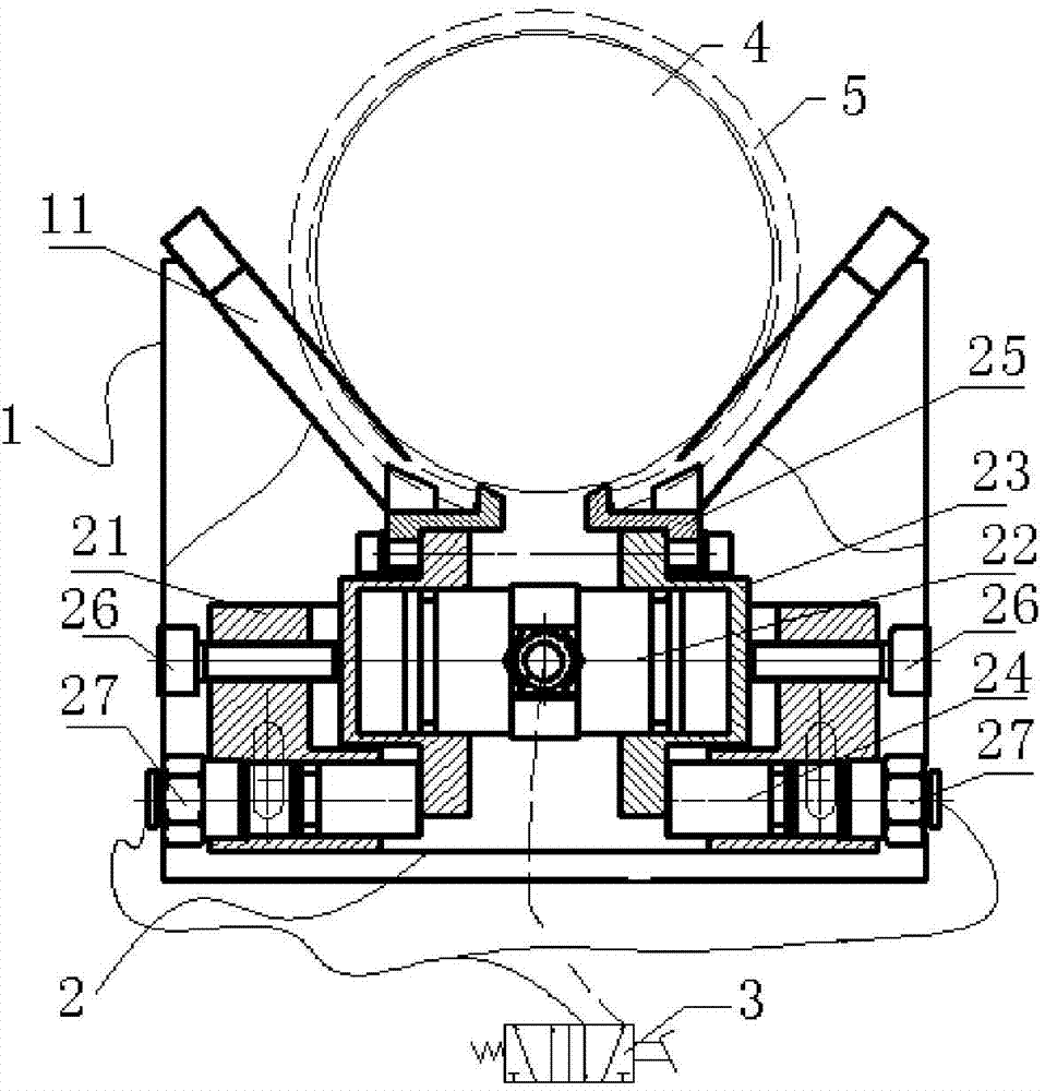
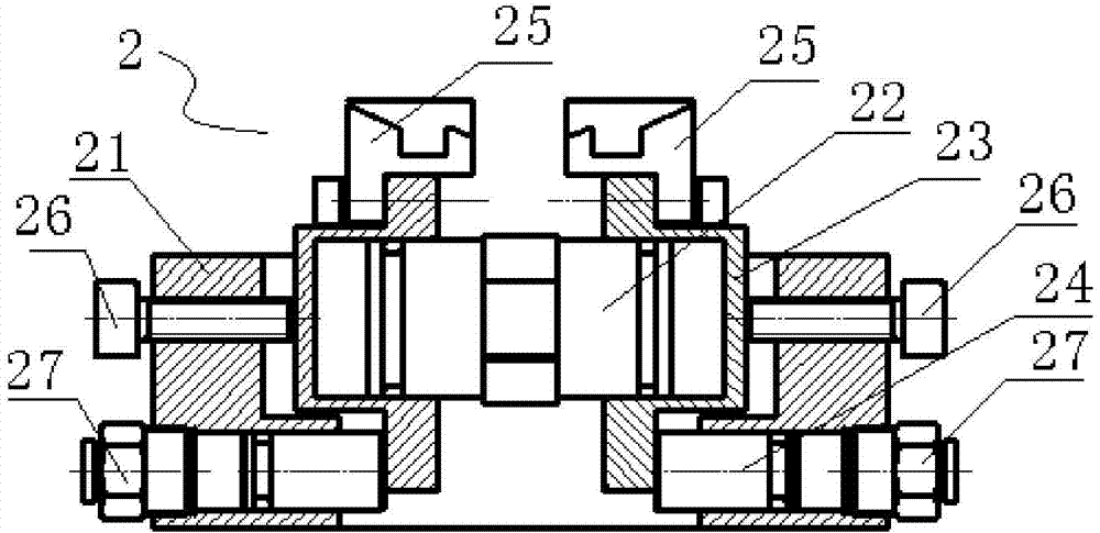
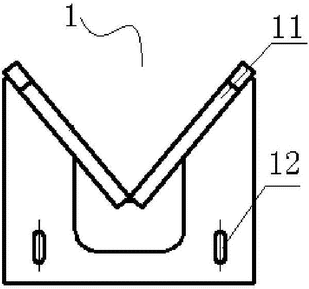
[0037] Such as figure 1 and figure 2 As shown, a piston ring assembly device according to a specific embodiment of the present invention includes a support frame 1 and a piston ring expansion assembly 2, wherein a V-shaped support plate 11 is provided above the support frame 1, and the V-shaped support plate 11 Used to support the piston 4 on which the piston ring 5 is to be installed. The height of the piston ring expa...


PUM


Abstract

The invention discloses an assembling device of a piston ring. The assembling device of the piston ring comprises a supporting frame and a piston ring stretching assembly. A V-shaped supporting plate used for supporting a piston of the piston ring to be assembled is arranged above the supporting frame. The piston ring stretching assembly comprises an installation base, a stretching air cylinder and two positioning blocks, wherein the installation base is of a square cavity, the two sides of the bottom end of the square cavity are provided with telescopic piston rods respectively, the stretching air cylinder comprises an air cylinder barrel and two air cylinder sleeves, the air cylinder sleeves are arranged at the two ends of the air cylinder barrel in a sliding fit mode respectively, the air cylinder sleeves are movably installed in the square cavity, the side wall of each air cylinder sleeve is provided with an upper step portion and a lower step portion, the ends of the two piston rods are correspondingly connected to the lower step portions in an abutting mode respectively, the two piston rods can drive the two air cylinder sleeves to be close to each other, the two positioning blocks are detachably arranged on the corresponding upper step portions respectively, the upper surface of each positioning block is provided with at least one fixing groove, hooks are arranged outside the fixing grooves, and the hooks on the two positioning blocks can be clamped into an opening of the piston ring at the same time. The assembling device can assemble multiple kinds of piston rings.

Description

technical field [0001] The invention relates to the field of mechanical tools, in particular to a piston ring assembly device. Background technique [0002] The assembly device of the piston ring is a common device for engine assembly. At present, two methods are generally used for actual assembly: one is to use the taper sleeve to open the piston ring, place the piston on the big end of the taper sleeve and use a numerically controlled stepping motor to axially The method of pushing the piston ring is realistically assembled. However, due to the different axial positions of the piston ring, multiple tapered sleeves and stepping motors need to be imported, which has a complex structure and a large investment; the other is to arrange the cylinder perpendicular to the piston ring surface, and use The semi-circular sleeve (tile) coupling the diameter of the piston and the position of the ring groove pushes the scraper on the arc surface to realize the opening of the piston ring...

Claims


Application Information

Patent Timeline
Patent Type & Authority Applications(China)
IPC IPC(8): B23P19/02
CPCB23P19/02
Inventor 吴培柱杨先恺潘长俊赵泽健杨秋
Owner GUANGXI YUCHAI MASCH CO LTD
Why Eureka
Try Eureka