Disposable detection device

A detection device and disposable technology, applied in the fields of application, medical science, surgery, etc., can solve the problems of patient discomfort, difficulty in entering the vagina, scratching the vaginal wall, etc., to avoid blind spots, avoid patient discomfort, and increase the viewing angle. Effect

Inactive Publication Date: 2021-09-24
陈光锁
View PDF0 Cites 0 Cited by
  • Summary
  • Abstract
  • Description
  • Claims
  • Application Information

AI Technical Summary

Problems solved by technology

[0004] The main purpose of the present invention is to overcome the deficiencies of the prior art, and provide a disposable detection device to solve the problem that the expansion of the appliance expands up and down, and the medical staff will have blind spots when inspecting, and the inspection is not in place. If the expansion size is increased, the clip It will be more difficult for the mouth to enter the vagina, causing discomfort to the patient, and may even scratch the vaginal wall in severe cases

Method used


Image

  • Disposable detection device
  • Disposable detection device
  • Disposable detection device

Examples


Embodiment 1

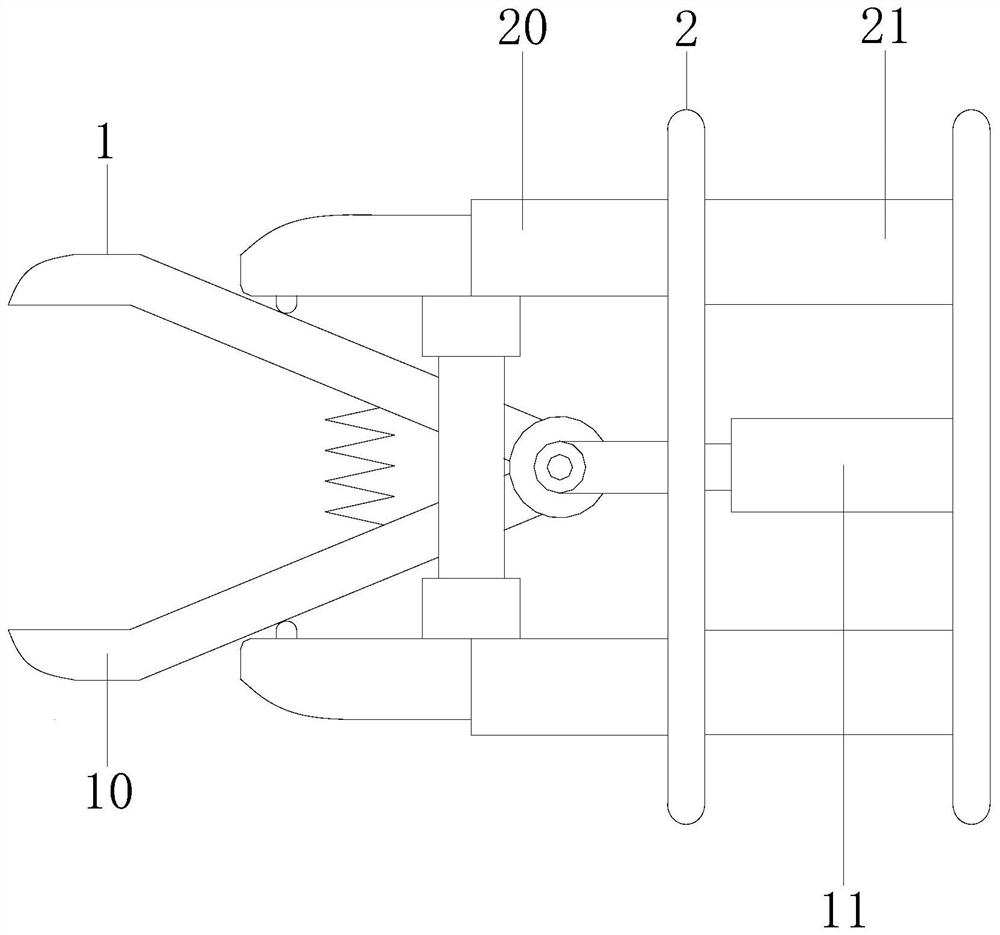
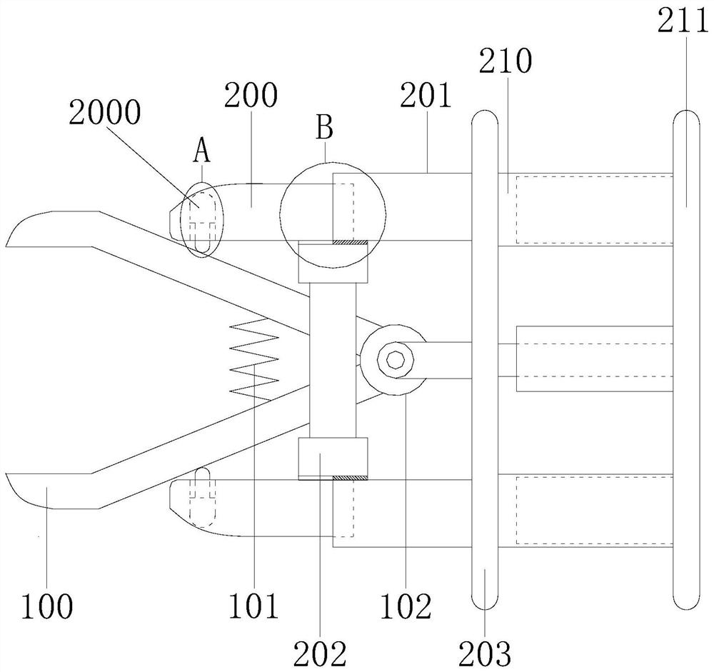
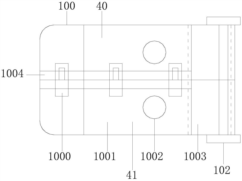
[0024] Example 1 see Figure 1-4 , the present invention provides a technical solution for a disposable detection device: its structure includes a clip structure 1 and a handle structure 2, the clip structure 1 and the handle structure 2 are assembled and connected, and the clip structure 1 includes a clip 10. Telescopic rod 11, the jaw 10 is axially connected to the telescopic rod 11, the handle structure 2 includes a front solid frame 20 and a rear solid frame 21, the front solid frame 20 and the rear solid frame 21 are welded, the The front solid frame 20 plays the role of reinforcing the jaw 10. The jaw 10 is composed of a jaw 100, a spring 101, and a clamp shaft 102. The upper and lower ends of the jaw 100 are welded to the upper and lower ends of the spring 101. The right end of the jaw 100 is Connected with the clamping shaft 102, the front solid frame 20 includes a clamping frame 200, a rail-to-frame 201, a back frame 202, and a middle plate 203. The clamping frame 200...

Embodiment 2

[0026] Example 2 see Figure 5 , 6 , the present invention provides a technical solution for a disposable detection device: the structure of the pendant 2000 includes an inner arch cavity 30, an inner spring 31, a rail slide 32, and a vertical rod 33, and the upper end of the inner spring 31 is connected to the inner arch cavity 30. The inner arc side is welded, the bottom end of the inner spring 31 is welded with the rail slide plate 32, the rail slide plate 32 is locked with the upper end of the vertical rod 33, the return frame 202 is equipped with an annular airbag 2020, and the pendant 2000 is connected with the clamp 10 Repulsive force is formed, the pendant 2000 reinforces the clamp 100, the return frame 202 is equipped with a left rail 2021, and the return frame 202 is welded with a welding plate 2022, and the left rail 2021 and the rail of the clamping frame 200 connection, the welding plate 2022 is welded to the rail to the frame 201.

[0027] When the pendant 2000...


PUM


Abstract

The invention discloses a disposable detection device. The device structurally comprises a clamping nozzle structure and a handle structure, the clamping nozzle structure and the handle structure are connected in a splicing mode, the clamping nozzle structure comprises a clamping nozzle and a telescopic rod, the clamping nozzle is in shaft connection with the telescopic rod, the handle structure comprises a front fixing frame and a rear fixing frame, the front fixing frame is welded to the rear fixing frame, and the clamping nozzle is composed of a forceps clip, a spring and a clamping shaft. The forceps clip is welded to both the upper end and the lower end of the spring, the right end of the forceps clip is in shaft connection with the clamping shaft, the front fixing frame comprises a clamping fixing frame, a rail-to-rail frame, a return frame and a middle plate, the clamping fixing frame is in rail connection with the rail-to-rail frame, the rail-to-rail frame is welded with the return frame, the rail-to-rail frame is locked with the middle plate, the clamping fixing frame is provided with a drooping device, the rear fixing frame comprises a telescopic rear frame and a tail plate, and the telescopic rear frame is locked with the tail plate. According to the invention, after the forceps clips are opened, an upper splicing plate and a lower splicing plate can move up and down along the tail end plate, the vaginal orifice is further expanded in a peripheral mode, visual dead angles are avoided, examination is more accurate, limiting is carried out while expansion is carried out, and discomfort of a patient caused by too large size expansion is avoided.

Description

technical field [0001] The invention relates to the field of gynecological equipment, in particular to a disposable detection device. Background technique [0002] Vaginal dilator is a commonly used medical device, which is often used in obstetrics and gynecology. It is mainly used to expand the vagina, so that the doctor can clearly check the situation of the vagina and its surrounding organs; the existing vaginal dilator is generally duckbill It is mainly composed of two upper and lower expansion sheet fixing devices that can rotate around the axis. [0003] In the prior art, the device expands up and down, and the medical staff will have blind spots during the inspection, and the inspection is not in place. If the expansion size is increased, it will be difficult for the clip to enter the vagina, causing discomfort to the patient, and may even scratch the vagina in severe cases. wall. Contents of the invention [0004] The main purpose of the present invention is to o...

Claims


Application Information

Patent Timeline
Patent Type & Authority Applications(China)
IPC IPC(8): A61B1/32A61B1/303
CPCA61B1/32A61B1/303
Inventor 陈光锁
Owner 陈光锁
Why Eureka
Try Eureka