Casing detection device and objective table thereof

A detection device and stage technology, applied in the detection field, can solve problems such as inconvenient use, complex structure of the detection device, and low detection efficiency

Inactive Publication Date: 2014-10-29
HANS LASER TECH IND GRP CO LTD +1
View PDF5 Cites 8 Cited by
  • Summary
  • Abstract
  • Description
  • Claims
  • Application Information

AI Technical Summary

Problems solved by technology

Therefore, the current detection device has a complicated structure and is inconvenient to use, so that the detection efficiency is not high

Method used


Image

  • Casing detection device and objective table thereof

Examples


Embodiment Construction

[0024] In order to facilitate the understanding of the present invention, the present invention will be described more fully below with reference to the associated drawings. Preferred embodiments of the invention are shown in the accompanying drawings. However, the present invention can be embodied in many different forms and is not limited to the embodiments described herein. On the contrary, these embodiments are provided to make the understanding of the disclosure of the present invention more thorough and comprehensive.

[0025] It should be noted that when an element is referred to as being “fixed” to another element, it can be directly on the other element or there can also be an intervening element. When an element is referred to as being "connected to" another element, it can be directly connected to the other element or intervening elements may also be present.

[0026] Unless otherwise defined, all technical and scientific terms used herein have the same meaning as...


PUM

PropertyMeasurementUnit
angleaaaaaaaaaa

Abstract

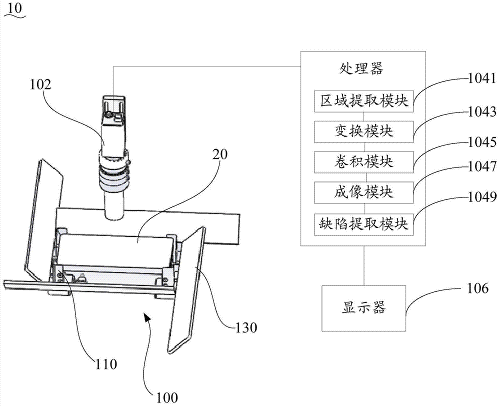
The invention provides a casing detection device which comprises an objective table, an image collector and a processor. The objective table comprises a fixed clamp and reflecting mirrors, the number of the reflecting mirrors is four, and the reflecting mirrors are arranged around the edge of the fixed clamp. In detection, the image collector is opposite to the front of a casing. Due to the fact that the reflecting mirrors and the supporting surface of the fixed clamp can form included angles of over 90 degrees, the image collector can simultaneously collect image information of the side edge of the casing in the four reflecting mirrors and image information of the front of the casing. Therefore, the front and the side of the casing can simultaneously undergo image collection only through one image collector. Due to the fact that only one image collector is used by the casing detection device, the casing detection device is simple in structure. Therefore, debugging does not need to be performed on a plurality of cameras in detection, the casing detection device is convenient to use, and accordingly casing detection efficiency is effectively improved.

Description

technical field [0001] The invention relates to detection technology, in particular to a casing detection device and its carrying platform. Background technique [0002] With the large-scale production and use of electronic products such as mobile phones, the quality requirements for the shell surfaces of various electronic products are also getting higher and higher. Therefore, after the processing of the shell is completed, the shell needs to be inspected to check whether there is any defect in the shell and whether the size meets the predetermined requirements. In the past, the human eye recognition method was generally used for recognition, which was low in efficiency and high in error. At present, in order to improve the detection efficiency, there is a detection device that analyzes the shell image through image processing software to detect whether the shell is qualified. However, current detection devices generally use multiple cameras to collect images of multiple...

Claims


Application Information

Patent Timeline
Patent Type & Authority Applications(China)
IPC IPC(8): G01B11/00G01N21/88
Inventor 舒远李玉廷王光能文茜米野丁兵高云峰
Owner HANS LASER TECH IND GRP CO LTD
Why Eureka
Try Eureka