
Image forming device

An image and paper technology, applied in the field of image forming devices, can solve problems such as unusable use and no warranty, and achieve the effect of reducing management costs

Inactive Publication Date: 2014-10-29
RICOH KK
View PDF6 Cites 2 Cited by
  • Summary
  • Abstract
  • Description
  • Claims
  • Application Information

AI Technical Summary

Problems solved by technology

[0008] The present invention is made to solve the above problems, and the purpose is to provide an image forming device that enables the fax unit to receive fax signals normally after the maintenance service is over. On the one hand, the user cannot continue to use the toner provided by the maintenance service provider for free. , which is beneficial to the interests of the maintenance service provider. On the other hand, the user can contact the maintenance service provider in time to renew the maintenance service, which can prevent the failure of the image forming device after the maintenance service expires. User's interests

Method used


Image

  • Image forming device
  • Image forming device
  • Image forming device

Examples


Embodiment

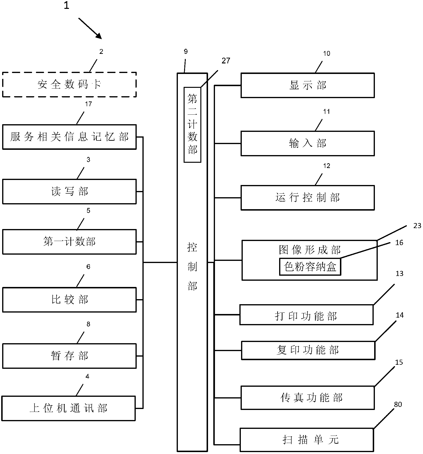
[0036] figure 1 It is a block diagram of the multifunctional printer in the embodiment of the present invention.

[0037] Such as figure 1 As shown, the multi-function printer 1, as an image forming device, can be provided by a maintenance service provider with maintenance services related to image formation, including a service-related information storage unit 17, a read-write unit 3, a host computer communication unit 4, and a first counting unit 5. Second counting unit 27, comparison unit 6, screen storage unit 7, temporary storage unit 8, display unit 10, input unit 11, operation control unit 12, printing function unit 13, copy function unit 14, facsimile function unit 15, The scanning unit 80, the notification section 22, the toner container 16, and the control section 9 for controlling the above-mentioned sections as a whole. The printing unit is composed of a printing function part 13 and a toner storage box 16 , the copying unit is composed of a copying function part...

Deformed example 1

[0132] Figure 8 It is a block diagram of a multifunctional printer according to Modification 1 of the present invention.

[0133] Such as Figure 8 As shown, the multi-function printer 201 may not have a secure digital card, but is provided with an external device communication unit 204 .

[0134] The external device communication part 204 is used for communicating with the upper computer, for receiving the file to be printed sent from the upper computer, obtaining the preset printing amount of paper used for printing according to the file to be printed, and converting the preset printing amount of the paper It is stored in the temporary storage unit 208 . The external device communication part 204 is also used to communicate with other external devices, and receives paper limit, paper use warning threshold, service contact basic information, service related operating procedures, notification screen, early warning screen, warning screen, service content screen, contact info...


PUM


Abstract

This invention pertains to an image formation device in which a fax unit can be made to receive a fax signal normally even after the expiration of a maintenance service. If a comparison performed by a comparison unit indicates that a paper usage amount has reached or exceeded a limiting paper amount, an operation control unit controls this image formation device such that an image formation unit only activates when a fax unit receives a fax signal. A user can thereby be easily made aware of the fact that a maintenance service has expired, and the user can thus promptly contact a maintenance-service provider and have a final maintenance service performed on the image formation device, making it possible to maintain the best possible performance from beginning to end. Another aspect is that the user can continue to use the fax unit normally and send and receive faxes even after the expiration of the maintenance service, preventing the user from being unable to receive important faxes and preventing delays in the user's fax operations.

Description

technical field [0001] The present invention relates to an image forming device, in particular to an image forming device which enables a fax unit to receive fax signals normally after the maintenance service is completed. technical background [0002] A Multi Function Printer (MFP) is an integrated office device that integrates multiple image forming functions such as printing, copying, scanning, and faxing. Because of its various functions and easy operation, it has been more and more widely used in office places. [0003] Unlike general household appliances, multifunction printers are composed of various precision parts whose performance will degrade over time and the number of times they are used, which may affect the quality of the final image formed. In addition, in the process of use, consumables such as toner and paper will also be consumed. Therefore, it is necessary to provide daily maintenance services such as cleaning, debugging or replacing parts, and replenis...

Claims


Application Information

Patent Timeline
Patent Type & Authority Applications(China)
IPC IPC(8): H04N1/00
CPCG03G15/553B41J29/17G03G15/502G03G15/55H04N1/33376
Inventor 大木勇
Owner RICOH KK
Learn More