Stabilizing pins after sheet metal forming

A metal sheet, post-stabilization technology, applied in the field of sheet metal stamping manufacturing, can solve problems such as poor adaptability, difficult debugging, etc., and achieve the effects of improving efficiency, simple structure, and ensuring stability

Active Publication Date: 2017-01-04
天津星原汽车零部件有限公司
View PDF8 Cites 0 Cited by
  • Summary
  • Abstract
  • Description
  • Claims
  • Application Information

AI Technical Summary

Problems solved by technology

Solve the problems of difficult debugging and poor adaptability

Method used


Image

  • Stabilizing pins after sheet metal forming
  • Stabilizing pins after sheet metal forming
  • Stabilizing pins after sheet metal forming

Examples


Embodiment Construction

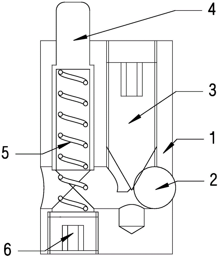
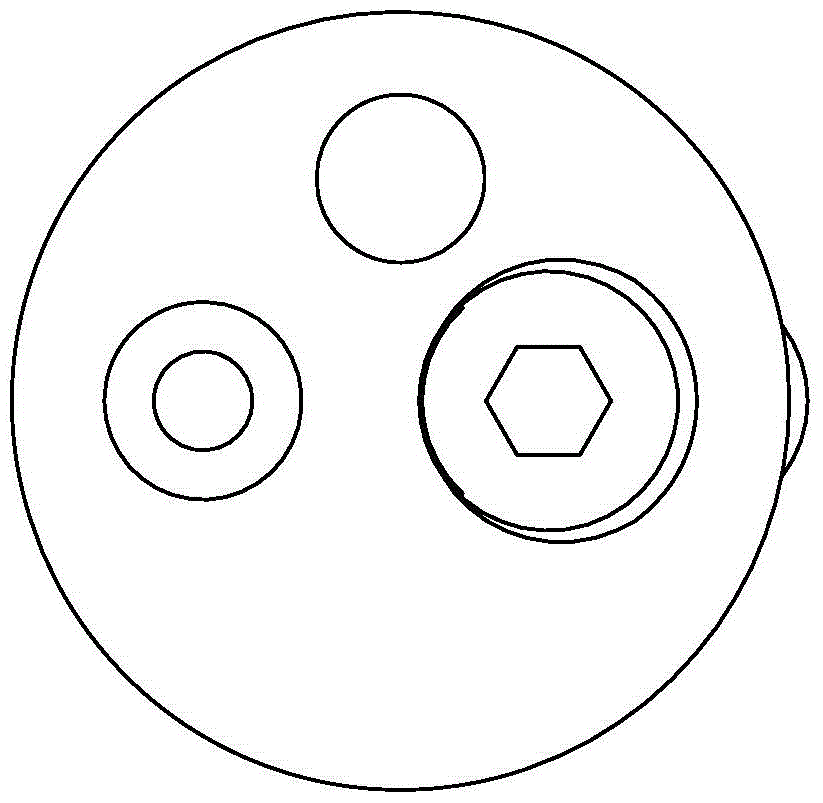
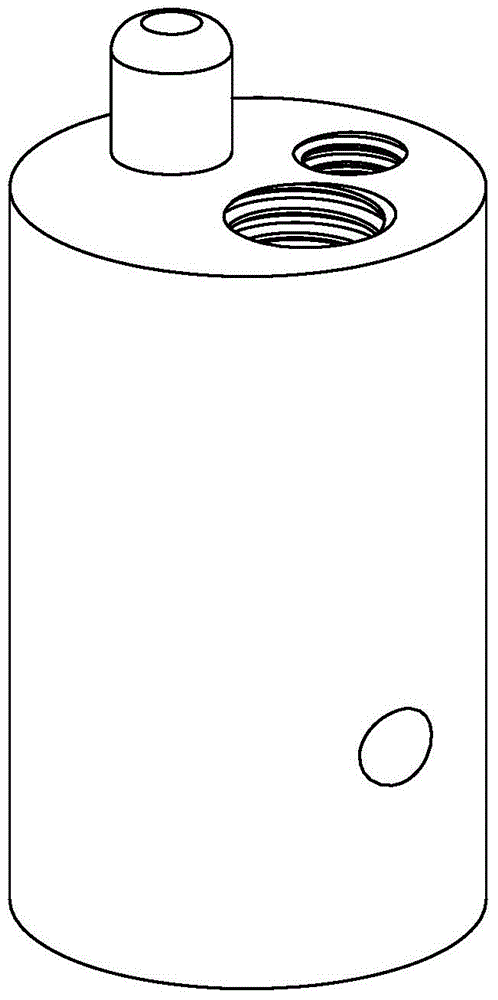
[0011] The specific implementation manner of the present invention will be described in detail below in conjunction with the accompanying drawings and preferred embodiments. as shown in the picture 1 to map 4 As shown, a sheet metal formed post-stabilizing pin, including a carrier 1 , positioning pin 4 ,spring 5 , screw plug 6 , steel ball 2 and taper threaded rod 3 . The steel ball is loaded into the carrier from the side, the positioning pin is loaded into the carrier from the back, and there are stepped holes to prevent and limit the position, the spring is loaded into the cavity behind the positioning pin, and the screw The plug is screwed into the carrier from the back to compress the spring, and the tapered threaded rod is screwed into the carrier from the front to compress the steel ball. There are hexagonal wrench grooves on the back of the screw plug and the tapered threaded rod, which are convenient for being screwed into the threaded hole. ...


PUM


Abstract

The invention belongs to the technical field of sheet metal stamping manufacturing, and particularly relates to a stabilizer pin after sheet metal forming, which is characterized in that it includes a carrier, a tapered threaded rod and a positioning pin, and the axial direction of the carrier is provided with a threaded hole and a positioning pin. Pin mounting holes, the positioning pin mounting holes are set eccentrically, and a stepped platform is provided in the positioning pin mounting holes, and the positioning pins enter the positioning pin mounting holes from the bottom of the carrier and are fixed by screw plugs , the back of the positioning pin is provided with a cavity, the spring is placed in the cavity, the bottom of the spring is against the plug; the side of the carrier is provided with a steel ball mounting hole, and the steel ball mounting hole is in contact with the screw plug. The threaded hole communicates with each other, and the front side of the tapered threaded rod is screwed into the threaded hole to compress the steel ball placed in the steel ball mounting hole. This structure is simple and easy to install, which effectively solves the problem of parts moving on the blank holder after stretch forming, thereby improving the efficiency of mold debugging and ensuring the stamping stability of the mold.

Description

technical field [0001] The invention belongs to the technical field of stamping and manufacturing of sheet metal, and in particular relates to a stabilizer pin after forming of sheet metal. Background technique [0002] When stamping, especially in automatic production, it is necessary to install positioning pins on the mold. The positioning pins need to be stuck on the edge of the stamping parts to prevent the parts from moving on the mold after forming, so as to obtain a stable position of the parts on the mold. , so as to meet the requirements of the automatic robot to send the parts to the subsequent mold according to the expected position, to ensure the normal operation of the stamping production, and to obtain products with stable dimensions. After the blank is drawn and formed, the boundary of the part needs to be restricted, but the drawn part boundary line cannot be accurately measured, and it needs to be determined through repeated tests during the mold debuggin...

Claims


Application Information

Patent Timeline
Patent Type & Authority Patents(China)
IPC IPC(8): B21D37/00
Inventor 张越鹏焦雷魁苏越
Owner 天津星原汽车零部件有限公司
Why Eureka
Try Eureka