A Lightweight Machine Tool Beam Reinforced by Arched Ribs

A light-weight, cross-beam technology, applied in the field of machine tools, can solve problems that do not conform to the force characteristics of the cross-beam, reduce the dynamic response of the cross-beam, and affect the dynamic characteristics of the machine tool, so as to improve the dynamic response characteristics, reduce the possibility, and increase the rigidity. Effect

Inactive Publication Date: 2017-01-04
XI AN JIAOTONG UNIV
View PDF5 Cites 0 Cited by
  • Summary
  • Abstract
  • Description
  • Claims
  • Application Information

AI Technical Summary

Problems solved by technology

Common forms of stiffeners include cross-shaped ribs, herringbone ribs, and rice-shaped ribs. These types of ribbed ribs can improve the overall stiffness of the beam, but there are two main problems: one is that no matter what type of rib The ribs are evenly distributed inside the beam, and the stiffness in the entire cross-section of the beam is the same, which does not conform to the force characteristics of the beam; secondly, because the ribs are evenly distributed inside the beam, resulting in tension at the supports at both ends of the beam Rib material is "redundant", which increases the total weight of the beam and reduces the dynamic response of the beam, which in turn affects the dynamic characteristics of the entire machine tool

Method used


Image

  • A Lightweight Machine Tool Beam Reinforced by Arched Ribs
  • A Lightweight Machine Tool Beam Reinforced by Arched Ribs
  • A Lightweight Machine Tool Beam Reinforced by Arched Ribs

Examples


Embodiment 1

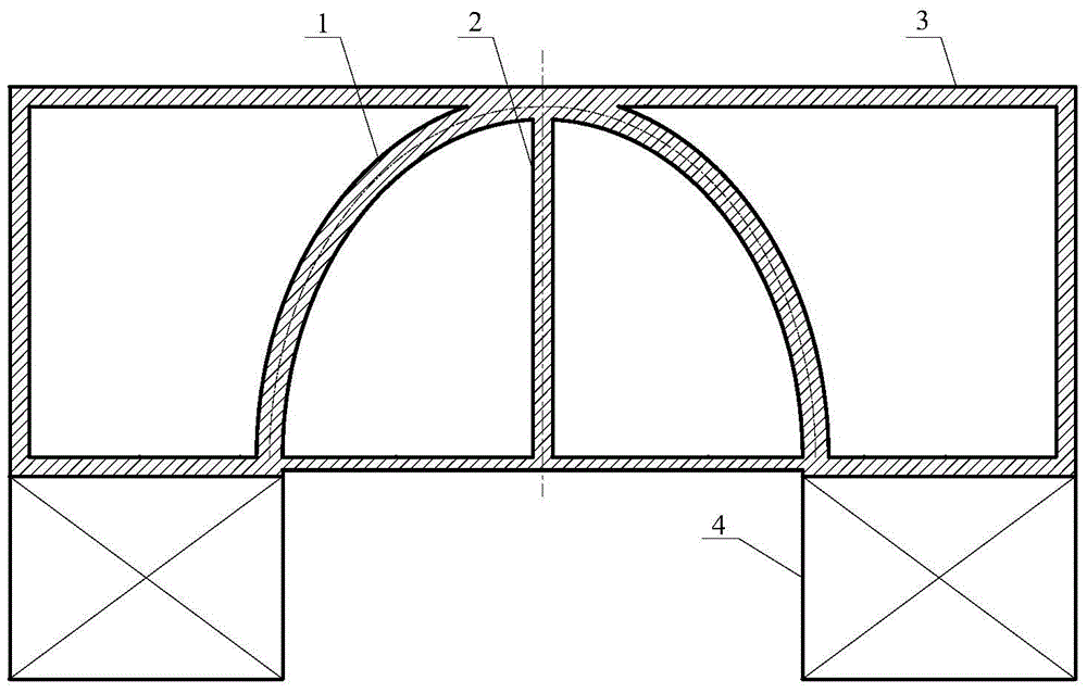
[0027] A light-weight machine tool beam reinforced by arch ribs, such as image 3 As shown, the chord-to-height ratio of the arch axis of the arched ribbed plate inside the beam is 1:1, and the arched ribbed plate has a strong bearing capacity. Only one longitudinal diaphragm is distributed in the center of the beam to improve the overall stiffness of the beam. At the same time, the weight of the beam is reduced, and the static and dynamic characteristics of the beam are improved.

Embodiment 2

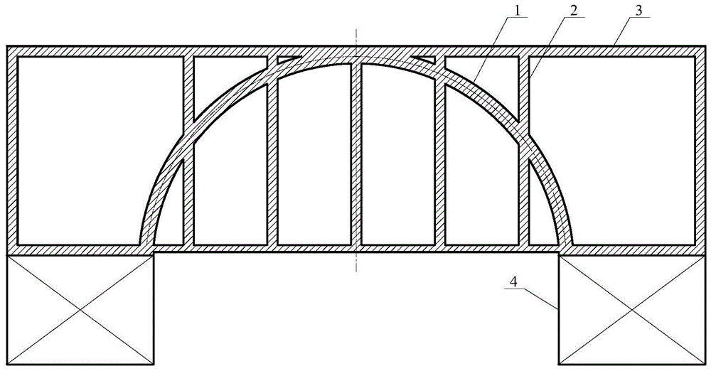
[0029] A light-weight machine tool beam reinforced by arch ribs, such as Figure 4 As shown, the chord-to-height ratio of the arch axis of the arched ribbed plate inside the beam is 2:1, and the arched ribbed plate has a strong load-carrying capacity. The three longitudinal diaphragms are distributed symmetrically on the basis, which can increase the overall stiffness of the beam, reduce the weight of the beam, and improve the static and dynamic characteristics of the beam.

Embodiment 3

[0031] A light-weight machine tool beam reinforced by arch ribs, such as Figure 5 As shown, the chord-to-height ratio of the arch axis of the arched stiffener plate inside the beam is 5:1, and nine longitudinal diaphragms need to be symmetrically distributed in the center of the beam with the mid-plane as the reference, so as to improve the overall stiffness of the beam and reduce the weight of the beam at the same time. Improve the static and dynamic characteristics of the beam.

[0032] The present invention compares the static characteristics of the cross ribbed beam and the arched ribbed beam, see Table 1 for details; see Table 2 for the comparison of dynamic characteristics.

[0033] Table 1 Comparison of static characteristics

[0034]

[0035] Table 2 Comparison of dynamic characteristics

[0036]

[0037] From Table 1 and Table 2, compared with cross-rib plate beams, it can be seen that the arched rib plate beams have the following performance improvements: th...


PUM


Abstract

The invention discloses a light-weight machine tool crossbeam reinforced with an arched rib plate. The interior adopts an arched ribbed plate, and a plurality of longitudinal diaphragms are symmetrically distributed based on the middle surface of the crossbeam. The crossbeam cross section is a rectangular cross section. The invention solves the problems of constant stiffness and material "redundancy" caused by the common stiffener plate inside the beam, increases the stiffness of the middle part of the beam, improves the dynamic characteristics of the beam, reduces the weight of the beam, and realizes Lightweight design. The beam cross-section adopts a widely used rectangular cross-section, which has a simple structure and is easy to install with other parts such as columns and carriages.

Description

technical field [0001] The invention belongs to the technical field of machine tools, and in particular relates to a light-weight machine tool crossbeam reinforced with arch ribs. Background technique [0002] The beam is an important basic component of the gantry machine tool, on which components such as the carriage and the headstock are connected. For large gantry machine tools, the size and span of the crossbeam are very large. Since the crossbeam is generally made of cast iron, its own weight is also very large, which can reach as many as several tons. The weight of the components such as the slide frame and the headstock connected to it is also very heavy. The total weight of the entire beam and the components connected to it can reach as much as tens of tons. Therefore, the beam is a basic component with a large load. The performance of the entire machine tool is greatly affected. On the one hand, due to its own weight and the weight of the parts connected to it, th...

Claims


Application Information

Patent Timeline
Patent Type & Authority Patents(China)
IPC IPC(8): B23Q1/01
Inventor 段玉岗邓发明邝连杰支勉
Owner XI AN JIAOTONG UNIV
Why Eureka
Try Eureka