Bottle blowing device for bottle blowing machine

A technology of bottle blowing machine and bottle blowing mould, which is applied in the field of bottle blowing devices, and can solve the problems of unsteady drive, poor control reliability, slow movement, etc., achieve accurate sequence and continuity, avoid bearing damage, and have no time difference in action Effect

Active Publication Date: 2014-11-05
JIANGSU FEIGE YOULIAN MACHIMERY
View PDF2 Cites 12 Cited by
  • Summary
  • Abstract
  • Description
  • Claims
  • Application Information

AI Technical Summary

Problems solved by technology

[0003] The disadvantages of the above-mentioned blowing device are: large number of pneumatic components, high cost, complicated control, any loose or damaged component will cause shutdown failure, poor reliability of interlock control of various actions, time difference in detection response, slow movement, use The direct drive of the cylinder is unstable, the impact force is large, and the gas consumption of multiple cylinders is large
In addition, the four-bar linkage mechanism is used when clamping the mold. There are many hinge points and high lubrication requirements. Once the oil filling operation is not in place, it is likely to cause damage to the bearings of the hinge points. Once the bearing is damaged, the weight of the four-bar linkage mechanism is heavy. , complex maintenance

Method used


Image

  • Bottle blowing device for bottle blowing machine
  • Bottle blowing device for bottle blowing machine
  • Bottle blowing device for bottle blowing machine

Examples


Embodiment Construction

[0034] The present invention will be described in further detail below through specific examples.

[0035] The front, back, left, and right described in the embodiment of the present invention are figure 1 The position placed in the center is determined, the left side of the observer is left, the right hand side is right, the front is close to the observer, and the back is far away from the observer.

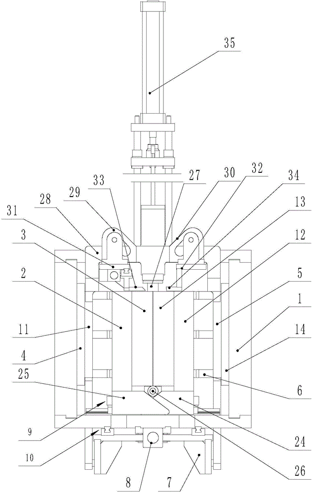
[0036] Such as Figure 1 to Figure 13 As shown, a bottle blowing device of a bottle blowing machine includes a frame, a bottle blowing mold, a preform input device, a bottle output device, a mold opening and closing device, an upper sealing device, a bottom mold lifting device, and an air blowing device.

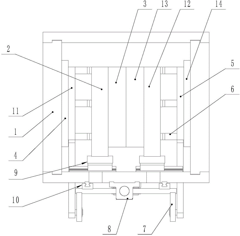
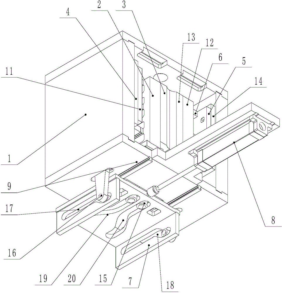
[0037] Such as Figures 2 to 5 As shown, the bottle blowing mold includes a mold frame 1, left and right mold bases 2, 12, left and right bottle body molds 3, 13, and a bottom mold 36. The mold frame 1 is fixed on the frame, and the mold frame 1 includes a bottom plate, a t...


PUM


Abstract

The invention discloses a bottle blowing device for a bottle blowing machine. The device comprises a mold frame, a left bottle body mold, a right bottle body mold, a left mold base, a right mold base, a left mold lock plate, a right mold lock plate, and a driving seat. The left and right mold lock plates are vertically and slidably arranged on the mold frame; mold lock blocks at intervals are arranged on the left and the right mold lock plates; the left and right mold seats are provided with embedding holes; the driving seat is driven by a power device; the driving seat is provided with a left mold opening and closing curve groove, a right mold opening and closing curve groove, a left mold lock curve groove and a right mold lock curve groove; the left and right mold seats are respectively provided with a mold opening and closing cooperation part constrained in the left mold opening and closing curve groove, the right mold opening and closing curve groove; and the left and right mold lock plates are respectively provided with a mold lock cooperation part constrained in the left and right mold lock curve grooves. The bottle blowing device uses the driving seat can be realize mold opening and closing and mold locking of the left and right bottle molds at the same time; and the whole bottle blowing action process reduces the number of cylinders, sensors and electromagnetic valves, saves cost, reduces the failure rate and repair, and is also very convenient.

Description

technical field [0001] The invention relates to a bottle blowing device, in particular to a bottle blowing device of a bottle blowing machine. Background technique [0002] In recent years, China's beverage industry has developed rapidly, and it has driven the rapid development of beverage machinery. The blow molding machine is a commonly used machine for producing beverage bottles in beverage machinery factories. Whether the blow molding device of the blow molding machine is stable and fast , is one of the important factors that affect the output and stability of the blow molding machine. The blow molding device of the blow molding machine generally includes the following actions: the preform is clamped by the feed claw and sent to the mold, the bottom mold of the clamping mechanism rises, and the closing The bottle body mold of the mold mechanism is closed, the mold locking mechanism is locked, the preform is released by the preform feeding claw, the head seal is connected...

Claims


Application Information

Patent Timeline
Patent Type & Authority Applications(China)
IPC IPC(8): B29C49/28B29C49/56B29C49/70B29C49/42
Inventor 杨新良谢明飞
Owner JIANGSU FEIGE YOULIAN MACHIMERY
Why Eureka
Try Eureka