
Wave field separating method and device

A wave field separation and wave number domain technology, applied in the field of oil and gas exploration, can solve problems such as low calculation efficiency, difficulty in effectively distinguishing the spatial structure of data points, and large calculation load

Inactive Publication Date: 2014-11-05
INST OF GEOLOGY & GEOPHYSICS CHINESE ACAD OF SCI
View PDF5 Cites 21 Cited by
  • Summary
  • Abstract
  • Description
  • Claims
  • Application Information

AI Technical Summary

Problems solved by technology

There are two main interpolation methods, one is to construct an analytic function linking the anisotropy parameter and the polarization vector to calculate the interpolation coefficient, but this function is established based on the theory of weak anisotropy, for strongly anisotropic media, there is The deviation will lead to interpolation problems. The other method is to use spatial interpolation, using the IDW (Inverse Distance Weights) algorithm. The IDW algorithm is based on the principle of similarity and similarity. It is greatly affected by non-uniformly distributed data points. More, the more accurate the interpolation is, but if the selected data points have the same distance, their weights are also the same, and it is difficult to effectively distinguish the spatial structure of the data points
[0006] However, in order to achieve good accuracy, the current processing of anisotropy is carried out in the spatial domain. Although the accuracy can be guaranteed in this way, the calculation amount is large and the calculation efficiency is relatively low.

Method used


Image

  • Wave field separating method and device
  • Wave field separating method and device
  • Wave field separating method and device

Examples


Embodiment Construction

[0058] In order to make the object, technical solution and advantages of the present invention clearer, the present invention will be described in further detail below in conjunction with the embodiments and accompanying drawings. Here, the exemplary embodiments and descriptions of the present invention are used to explain the present invention, but not to limit the present invention.

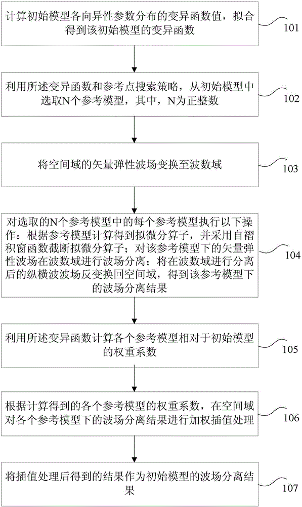
[0059] In this example a wavefield separation method is proposed as figure 1 shown, including the following steps:

[0060] Step 101: Calculate the variation function value of the anisotropic parameter distribution of the initial model, and obtain the variation function of the initial model by fitting;

[0061] Step 102: Using the variation function and the reference point search strategy, select N reference models from the initial model, where N is a positive integer;

[0062] Step 103: Transform the vector elastic wave field in the space domain to the wavenumber domain;

[0063] Step 104: ...


PUM


Abstract

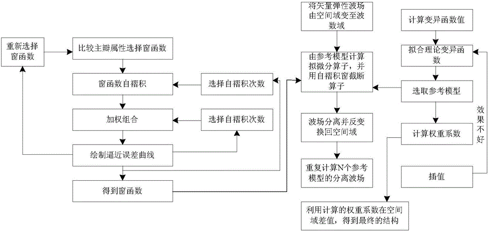
The invention provides a wave field separating method and device. The method comprises the steps that variation function values of anisotropy parameter distribution of initial models are calculated and fitted to obtain variation functions of the initial models; the variation functions and a reference point search strategy are utilized for selecting N reference models from the initial models; a vector elastic wave field of a spatial domain is converted into a wave number domain; following operation is carried out on each reference model selected from the N reference models, pseudo differential operators are truncated, the wave field separation is carried out on the wave number domain, the vertical and horizontal wave field is reversely converted into the spatial domain, and the wave field separation results of the reference models are obtained; the variation functions are utilized for calculating the weight coefficients of all the reference models relative to the initial models; weighting interpolation processing is carried out on the wave field separation results of all the reference models in the spatial domain to obtain the wave field separation results of the initial models. According to the method, on the basis of ensuring the accuracy of the wave field separation results, the effect of reducing the calculation amount is achieved.

Description

technical field [0001] The invention relates to the technical field of oil and gas exploration, in particular to a wave field separation method and device. Background technique [0002] With the deepening of oil and gas exploration, the demand for higher-precision imaging and inversion is becoming more and more urgent. Conventional P-wave seismic exploration is widely used, but its imaging accuracy is not enough for specific complex geological structures. Therefore, the development of multi-wave and multi-component seismic exploration technology based on elastic wave theory has certain practical significance. Elastic vector wave field reverse time migration technology adopts full-wave wave equation, which will obtain richer detailed information. No matter in isotropic medium or anisotropic medium, the imaging effect of elastic vector wave on underground medium is better than that of Pure sonic imaging effect. However, one of the biggest problems faced by elastic wave rever...

Claims


Application Information

Patent Timeline
Patent Type & Authority Applications(China)
IPC IPC(8): G01V1/28G01V1/36
Inventor 王之洋刘洪
Owner INST OF GEOLOGY & GEOPHYSICS CHINESE ACAD OF SCI
Learn More