A Machine Tool Incentive Method Based on Cutting Protrusions with Gradual Varying Width

A boss and machine tool technology, applied in the direction of digital control, electrical program control, etc., can solve the problems of safe machine tool damage, complicated installation, unable to meet the needs of effective excitation of the machine tool, etc., and achieve the effect of reducing the cost of excitation.

Active Publication Date: 2017-02-01
HUAZHONG UNIV OF SCI & TECH
View PDF2 Cites 0 Cited by
  • Summary
  • Abstract
  • Description
  • Claims
  • Application Information

AI Technical Summary

Problems solved by technology

[0005] At present, the excitation of all machine tool modes in the frequency band of interest is mainly hammer or vibration exciter excitation. However, each component of the machine tool equipment has a large mass. If the percussion force is too high, it may cause damage to the equipment; if a vibrator is used for excitation, the power of a conventional vibrator is also difficult to excite the required mode, and the super-power vibrator not only has a low excitation frequency, it is difficult to meet the machine tool frequency. characteristic requirements, but also expensive and complicated to install
Moreover, hammers and exciters can only be used to excite the machine tool under static conditions, and the percussion or vibration exciter vibration of the machine tool will cause serious safety and machine tool damage risks
Therefore, traditional incentive methods cannot meet the needs of effective incentives for machine tools under working conditions.

Method used


Image

  • A Machine Tool Incentive Method Based on Cutting Protrusions with Gradual Varying Width
  • A Machine Tool Incentive Method Based on Cutting Protrusions with Gradual Varying Width
  • A Machine Tool Incentive Method Based on Cutting Protrusions with Gradual Varying Width

Examples


Embodiment Construction

[0032] In order to make the object, technical solution and advantages of the present invention clearer, the present invention will be further described in detail below in conjunction with the accompanying drawings and embodiments. It should be understood that the specific embodiments described here are only used to explain the present invention, not to limit the present invention.

[0033] In this embodiment, the method of the present invention is preferably described by taking the XHK5140 vertical machining center as an example.

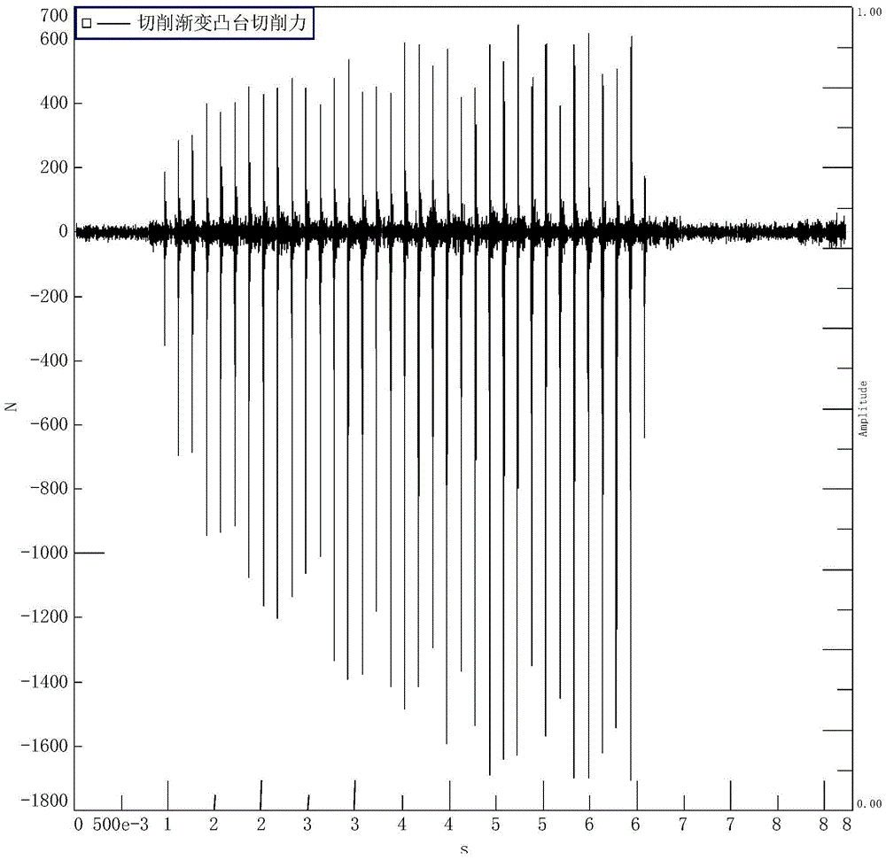
[0034] For the XHK5140 vertical machining center, the processing method is mainly milling, and the pulse cutting is realized by milling a single gradual boss. .

[0035] In this embodiment, the machine tool excitation method based on cutting a gradual boss workpiece includes the following steps:

[0036] (1) Design the gradual width of the workpiece boss: narrow end width a nw and big endian width a bw (in the present embodiment, the unit is pre...


PUM


Abstract

The invention discloses a machine tool excitation method based on the cutting of a boss work piece with gradually changing width. A boss work piece with gradually changing width is cut by cutter teeth to generate a pulse force with gradually changing pulse width to excite a machine tool. The method comprises the following steps: (1) the gradually changing widths of a work piece boss are determined, including a narrow-end width anw and a large-end width abw; (2) the length al of the work piece boss is determined; (3) a boss work piece is machined according to the length and width parameters; and (4) the boss work piece is cut by cutter teeth according to the rotation speed n, the feed rate af and the back engagement ap of cutter teeth of a machine tool, the cutting force between a cutter and a gradually changing boss applies a pulse excitation signal to a machine tool structure so as to generate a pulse cutting force with gradually increasing pulse width and amplitude to excite the machine tool. The method of the invention not only can greatly reduce the excitation cost of modal test, but also can be adopted to excite a machine tool in a controlled way according to the needs and specific objects in the working state to obtain the dynamic characteristics of the machine tool in the working state.

Description

technical field [0001] The invention belongs to the field of dynamic analysis of mechanical equipment structures, and in particular relates to a machine tool excitation method. Background technique [0002] The dynamic characteristics of the machine tool are very important to improve its processing performance and optimize its structural design. [0003] At present, the main method to obtain the dynamic characteristics of the machine tool structure is the experimental modal analysis method based on artificial excitation under the static state of the machine tool. The main feature of this method is to apply a specific excitation force to the machine tool structure to stimulate the dynamic characteristics of the machine tool, that is, the machine tool mode, and simultaneously measure the excitation force and the vibration response of the machine tool structure to identify the machine tool mode. state to characterize the dynamic characteristics of the machine tool structure. ...

Claims


Application Information

Patent Timeline
Patent Type & Authority Patents(China)
IPC IPC(8): G05B19/18
Inventor 李斌毛新勇蔡辉闫睿智罗博张译寒刘响球潘大为彭芳瑜
Owner HUAZHONG UNIV OF SCI & TECH
Why Eureka
Try Eureka