Planetary gear device and driving component with same

A technology of planetary gears and planetary gear racks, applied to components with teeth, gear transmissions, transmission parts, etc., can solve problems such as large structural space and achieve the effect of simple structure

Inactive Publication Date: 2006-01-11
ZF FRIEDRICHSHAFEN AG
View PDF2 Cites 0 Cited by
  • Summary
  • Abstract
  • Description
  • Claims
  • Application Information

AI Technical Summary

Problems solved by technology

The disadvantage here is that the transmission overall requires more installation space in the axial direction, since the two bearings of the bearing pair have to be installed spatially next to the planetary gear set on the output side, but in the area of ​​the input shaft. leaving unused ready-made structural space

Method used


Image

  • Planetary gear device and driving component with same
  • Planetary gear device and driving component with same
  • Planetary gear device and driving component with same

Examples


Embodiment Construction

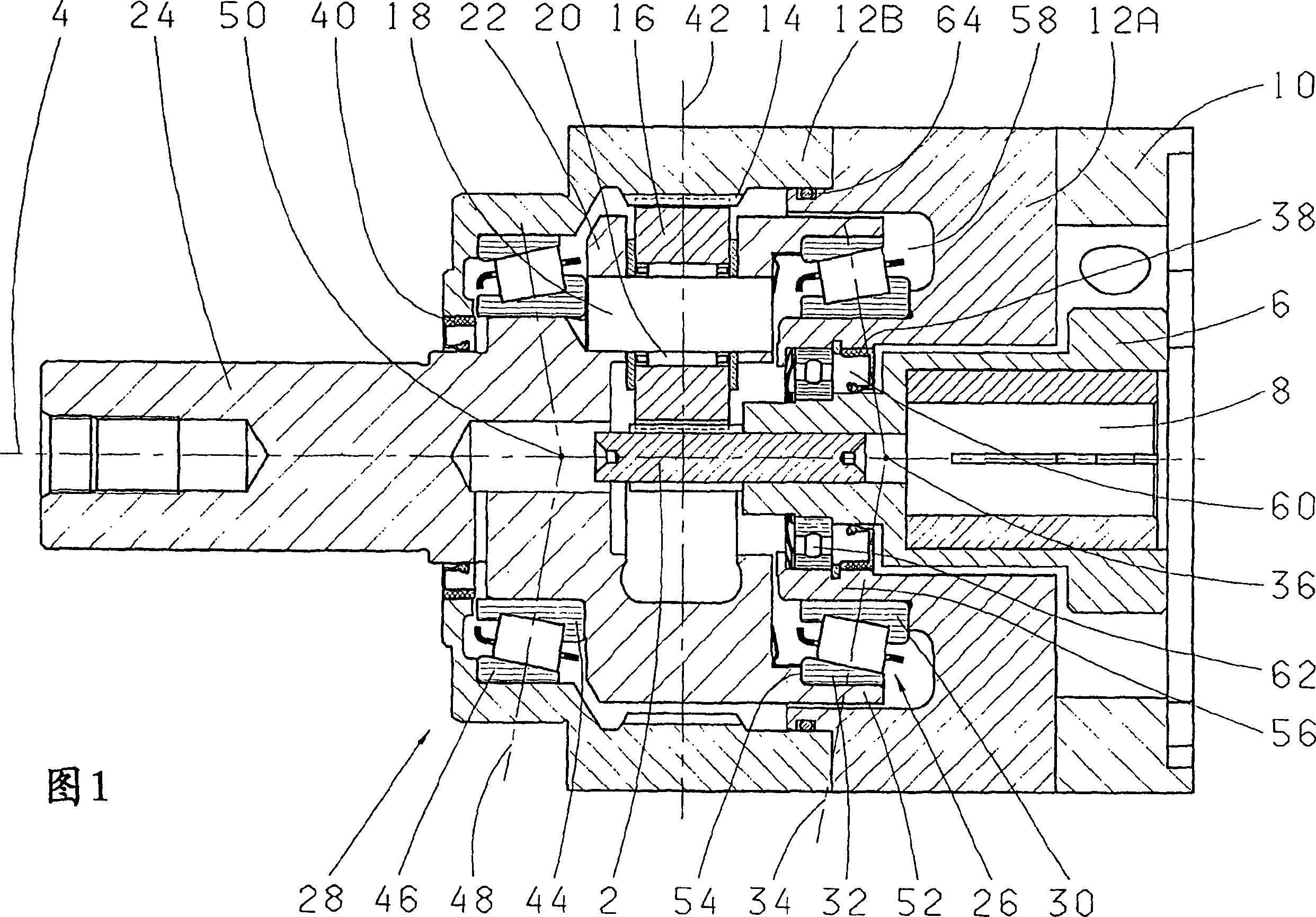
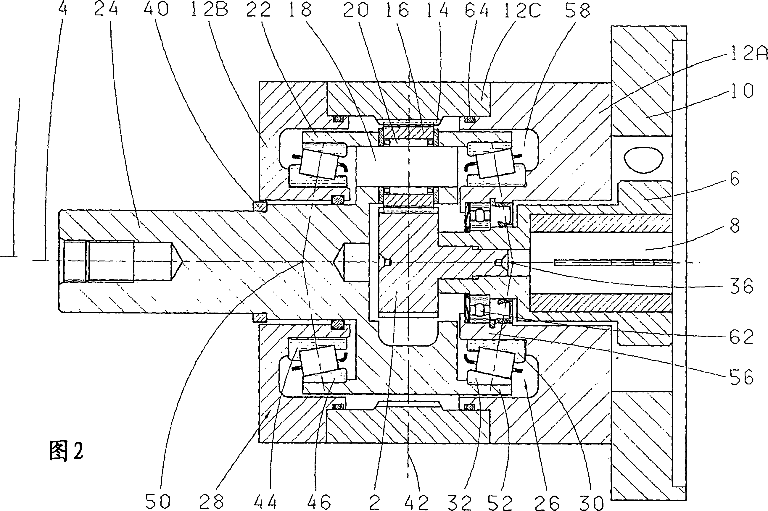
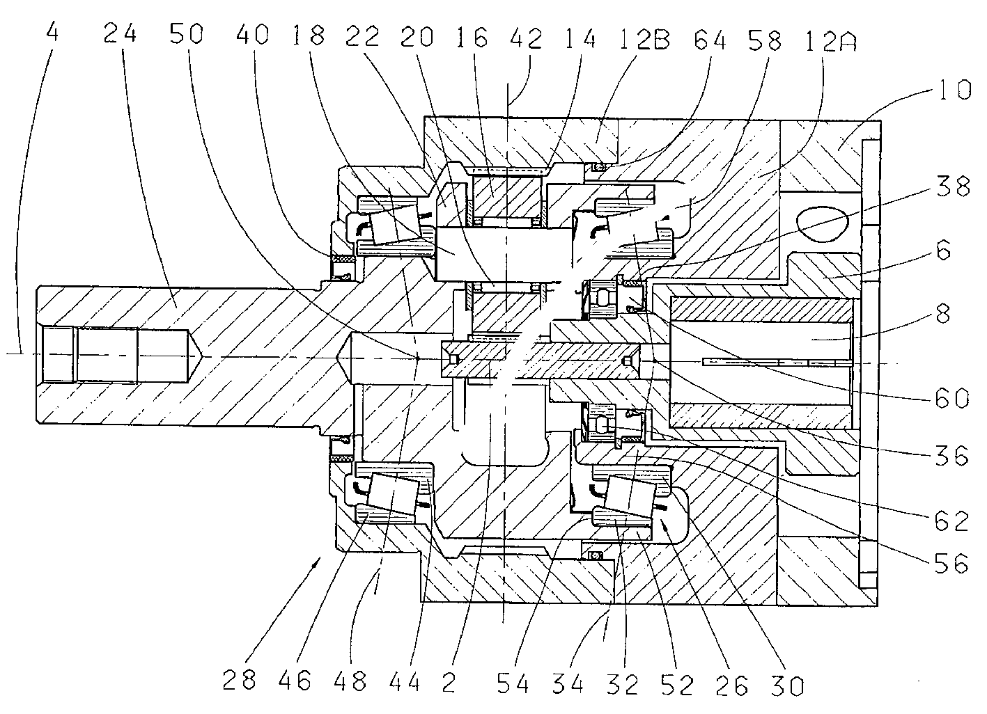
[0018] A sun gear coaxial with the main axis 4 of the transmission is denoted by 2 in FIG. 1 . The sun gear 2 is fixedly connected in rotation with the sun gear shaft 6, and the sun gear shaft has a mounting area 8, which is used for a motor not shown in the figure that can be mounted on the motor flange 10 through a flange. motor shaft. The housing of the planetary gear unit consists of two housing parts 12A, 12B. A hollow gear 14 is machined in the housing part 12B. A plurality of planet gears 16 (only one of which is shown) are rotatably supported on planet gear pins 18 via planet gear bearings 20 . The planet pins 18 or the planet gears 16 are arranged distributed over the circumference of the planet carrier 22 and mesh simultaneously with the sun gear 2 and the hollow gear 10 . The planet carrier 22 forms the driven device and is designed in one piece with the output shaft 24 . However, the planet carrier and the output shaft can also be connected via a rotationally f...


PUM


Abstract

A ring gear (14) is fixed in a housing (12A,B) in which a planetary cage (22) is pivot mounted . Planetary wheels (16) are distributed around the periphery of the planetary cage and has teeth engaging with the sun wheel (2) and ring gear. The planetary cage forms the main drive pinion and is mounted, together with a driven-side driven shaft (24) inside the housing, by an axial pair (26,28) of slanted bearings. At least the first slanted bearing with its inner ring (30) is fixed in the housing, and, with its outer ring (32), circulates with the planetary cage, to form a pressure-cone with its pressure-lines (34).

Description

technical field [0001] The present invention relates to a planetary gear device, comprising a sun gear coaxial with the main axis of the transmission device and supported rotatably, a hollow gear fixed in the casing and a planetary gear carrier rotatably mounted in the casing, A plurality of planetary gears are distributed and rotatably supported on the planetary gear carrier, and they are in tooth mesh with the sun gear and the hollow gear at the same time, wherein the planetary gear carrier constitutes a driven device and is connected to an output shaft on the driven side Together, they are supported inside the housing by an axially mounted radial thrust bearing pair consisting of a first radial thrust bearing and a second radial thrust bearing. Background technique [0002] This type of planetary gear unit, in which the planetary gear carrier forms the output unit and is supported together with the output shaft on the output side via an axially mounted radial thrust beari...

Claims


Application Information

Patent Timeline
IPC IPC(8): F16H1/28F16H1/36F16C19/36F16C19/54F16C35/06F16H57/02F16H57/08
CPCF16C19/364F16C19/548F16C2361/61F16H57/08F16C35/06F16H1/28
Inventor 霍斯特·舒尔茨蒂诺·基施纳
Owner ZF FRIEDRICHSHAFEN AG
Why Eureka
Try Eureka