Microparticle Manufacturing Method

A manufacturing method and particle technology, applied in separation methods, chemical instruments and methods, crystallization regulation/control, etc., can solve problems such as reduction in processing flow, and achieve low-cost effects

Active Publication Date: 2017-03-08
M TECH CO LTD
View PDF7 Cites 0 Cited by
  • Summary
  • Abstract
  • Description
  • Claims
  • Application Information

AI Technical Summary

Problems solved by technology

[0005] However, even in the case of using the method described in Patent Document 3, when it is desired to nucleate particles between the processing surfaces and complete subsequent growth, in order to secure the particle raw material fluid and the solvent for precipitation In the residence time between the above-mentioned processing surfaces, it is sometimes necessary to reduce the processing flow rate, especially when scaling up, there is a problem that a large device is required.

Method used


Image

  • Microparticle Manufacturing Method
  • Microparticle Manufacturing Method
  • Microparticle Manufacturing Method

Examples


Embodiment 1

[0147]As Example 1, the discharge liquid of the seed crystal particles containing nickel particles discharged from between the processing surfaces 1 and 2 was collected in one container for 20 seconds under the above-mentioned conditions. During the recovery, it was confirmed that the discharge liquid changed from a yellow-green turbid state to a black state, and the recovery was carried out for 20 seconds. After the recovery was completed for about 20 seconds, the change in the color of the discharge liquid disappeared visually. The temperature of the discharge liquid at this time was 95°C. In order to collect the fine nickel particles, the discharge liquid was allowed to stand still at room temperature. Thereafter, nickel fine particles were precipitated, and the supernatant was removed, followed by washing with pure water three times, and drying under atmospheric pressure at 25°C. As a result of XRD measurement of the dried nickel microparticle powder, it was confirmed tha...

Embodiment 2

[0151] As Example 2, as in Example 1, the effluent discharged from between the treatment surfaces 1 and 2 in Example 1 was collected in one container for 20 minutes. During the recovery, it was confirmed that the effluent changed from a yellow-green turbid state to black, and about 40 seconds after the start of recovery, the change in the color of the effluent disappeared visually, and the temperature of the effluent at this time was 95°C. Nickel fine particles were recovered by the same operation as in Example 1, and XRD measurement and SEM observation were performed. As a result of the XRD measurement, it was confirmed that homogeneous nickel without impurities was produced. Figure 6 A SEM photograph of the nickel fine particles obtained in Example 2 is shown. From Figure 5 , 6 Confirmation: Compared with Example 1, inhomogeneous microparticles with inconsistent particle diameter uniformity were produced.

Embodiment 3

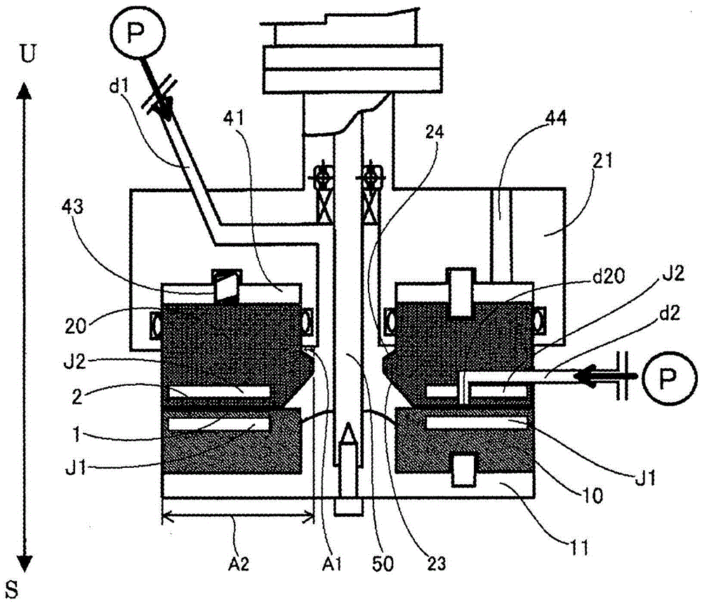
[0155] As Example 3, such as Figure 4 As shown in the fluid treatment device of , a vessel 61 connected to a tubular container 62 for collecting the discharge liquid is provided. In addition, the diameter of the tubular container and the length of the tubular container are set such that the residence time of the discharge liquid in the tubular container 62 is 20 seconds or more. In addition, the tubular container 62 is immersed in an oil bath 65 . Under the same conditions as in Example 1, the nickel solution and the reducing agent solution are mixed in the thin film fluid produced between the faces 1 and 2, and the fluid containing the seed crystal particles of the nickel particles is used as the discharge liquid from the face 1 , 2 discharges, the discharge liquid is continuously introduced into the tubular container 62 from the inlet 63 of the tubular container, and discharged from the outlet 64 of the tubular container. The discharge liquid is continuously discharged wi...


PUM

PropertyMeasurementUnit
particle diameteraaaaaaaaaa

Abstract

An object of the present invention is to provide a method for producing fine particles. A method for producing microparticles is provided. As the first step, in the film fluid formed between at least two processing surfaces that are arranged oppositely, that can be approached and separated, at least one of which is relatively rotated relative to the other, the seed crystal particles are precipitated, and the The fluid containing the precipitated seed crystal particles is discharged as a discharge liquid. Thereafter, as a second step, the precipitated seed crystal particles are grown in the discharged effluent to obtain target particles. In the method for producing fine particles, uniform and homogeneous fine particles are obtained by including the above-mentioned two steps.

Description

technical field [0001] The present invention relates to a method for producing microparticles. Background technique [0002] Microparticles such as metals, oxides, pharmaceuticals, foods, cosmetics, and other living body ingestible substances, and pigments are required in a wide range of fields in the industry. [0003] The method of producing microparticles generally uses a batch process method using a reaction vessel such as a flask, a beaker, or a tank for reactions such as a poor solvent method, crystallization, oxidation, and reduction. However, in the batch method, the concentration and temperature in the reaction vessel are likely to become uneven, and nucleation and subsequent nuclei growth are also likely to become uneven, so the particle size distribution of the resulting fine particles becomes wider. . Therefore, as in Patent Document 1, a method of making the size of precipitated particles uniform by adding a substance called a seed crystal nucleus into a react...

Claims


Application Information

Patent Timeline
Patent Type & Authority Patents(China)
IPC IPC(8): B01J19/00B22F9/24
CPCB22F9/24B01J19/1887B01J2219/00076B01J2219/00103B01F2215/0409B01F2215/0431B01F2215/0481B01D9/0054B01D9/0063B01D9/0072B01F27/2712B22F9/16C22B11/04C22B23/04
Inventor 榎村真一
Owner M TECH CO LTD
Why Eureka
Try Eureka