
An explosive combination device for directional cutting blasting in open-pit mines

A technology of cutting blasting and combination device, applied in blasting and other directions, can solve the problems of difficult positioning of charge packs, low efficiency, and difficulty in deep-hole charging, and achieve the effects of simple and convenient charging, improving construction efficiency, and improving economic benefits.

Active Publication Date: 2016-08-24
SINOSTEEL MAANSHAN INST OF MINING RES CO LTD +2
View PDF5 Cites 0 Cited by
  • Summary
  • Abstract
  • Description
  • Claims
  • Application Information

AI Technical Summary

Problems solved by technology

[0004] (1) The charges of the explosive energy-gathering blasting method need special processing, which is difficult and inefficient for deep hole charging, and it is difficult to position the charge in the blast hole, and the energy-gathering direction of the explosive cannot be guaranteed
[0005] (2) Grooving stress concentration type Cutting blasting needs to cut grooves on the hole wall. For deep hole cutting holes, it is difficult to cut grooves on the hole wall and ensure directionality; therefore, it has not been widely used.
However, this technique has not been used for directional cutting blasting in open pit mines

Method used


Image

  • An explosive combination device for directional cutting blasting in open-pit mines
  • An explosive combination device for directional cutting blasting in open-pit mines
  • An explosive combination device for directional cutting blasting in open-pit mines

Examples


Embodiment Construction

[0022] In order to further describe the present invention, an explosive combination device for directional cutting blasting in open-pit mines of the present invention will be further described below in conjunction with the accompanying drawings and examples.

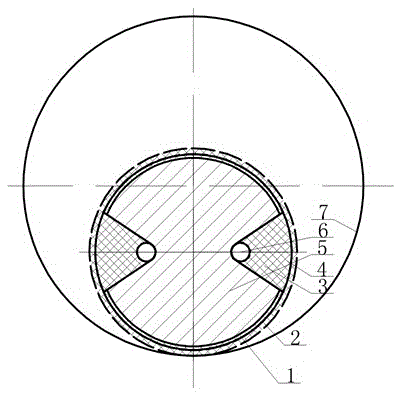
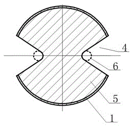
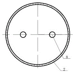
[0023] Depend on figure 1 Shown is a schematic diagram of the cross-sectional structure of an explosive combination device used for directional cutting blasting in open-pit mines of the present invention and combined with figure 2 , Figure 5 It can be seen that the explosive combination device is placed in the inclined cutting hole 7 of the open-pit mine slope, and it is composed of several sections of explosive devices connected in series through detonating cords 6, and each meter of detonating cords 6 is connected in series with 2 to 4 sections of explosive devices. Section explosive device contains charge tube 1, the explosive 5 that is contained in charge tube 1. Both sides of the charge tube 1 are symmetrically ...


PUM


Abstract

The invention discloses an explosive combination device for directional cutting blasting in open-pit mines. It is composed of several explosive devices connected in series through detonating cords (6). Each explosive device contains a charging tube (1), mounted on Explosives (5) in the charge tube (1); energy gathering grooves (4) are arranged symmetrically on both sides of the charge tube (1); plugging covers (2) are respectively installed at both ends of the charge tube (1) , two reserved holes (8) are set on each plugging cover (2); two detonating cords (6) pass through the reserved holes of the upper and lower ends of the charging tube (1) respectively (8); A rubber strip (3) is installed in the plugging cover (2) along the direction of the groove of the energy-gathering groove (4). The invention is suitable for shallow hole or deep hole cutting and blasting, can carry out cutting groove orientation, charge is simple and convenient, and explosives can be loaded into the directional charge tube in advance, which improves the construction efficiency on site and can increase the distance between cutting holes by about 10%; It can be widely used in slope protection in engineering blasting fields such as open-pit mines, hydropower and hydropower, and railway transportation.

Description

technical field [0001] The invention belongs to the technical field of engineering blasting, and in particular relates to a directional cutting blasting explosive structure, which is suitable for directional cutting blasting or pre-splitting blasting in open-pit mines and engineering blasting protection slopes. Background technique [0002] Prediction and control of blasting hazards has always been an important research topic in the field of engineering blasting, among which the earthquake hazards of blasting have attracted the most attention. , mines and other engineering construction can be widely used. [0003] Cutting blasting is developed on the basis of pre-splitting blasting. It was originally applied to the cutting of stone materials. Grooves are made on the hole wall in the direction of the cutting seam of the cutting hole or the powder roll is processed into an energy-gathering cave in the direction of the cutting seam. The extremely high stress wave and explosive...

Claims


Application Information

Patent Timeline
Patent Type & Authority Patents(China)
IPC IPC(8): F42D1/08
Inventor 刘为洲杨海涛张西良崔正荣谢亮波王铭袁光明黄凯和江东平仪海豹顾红建
Owner SINOSTEEL MAANSHAN INST OF MINING RES CO LTD
Learn More