
Method and device for controlling user terminal uplink transmission power

A technology of user terminal and transmission power, applied in the field of communication, can solve problems such as poor cell edge performance and avalanche effect, and achieve the effect of avoiding avalanche problems

Active Publication Date: 2018-04-27
ALCATEL LUCENT SHANGHAI BELL CO LTD
View PDF4 Cites 0 Cited by
  • Summary
  • Abstract
  • Description
  • Claims
  • Application Information

AI Technical Summary

Problems solved by technology

[0005] Eventually, the uplink transmission power of many user terminals reaches the maximum value, and thus leads to an avalanche effect of uplink transmission power control
In this case, the IoT of each cell will be very high, and the cell edge performance of the whole system will be very poor

Method used

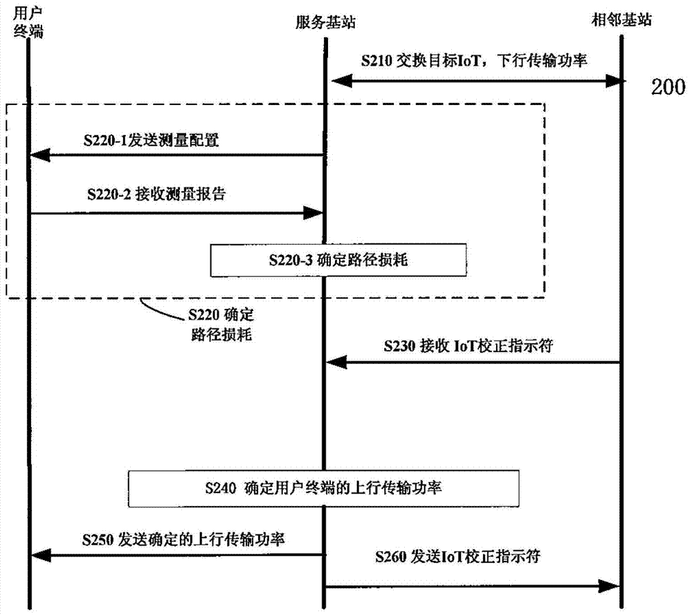
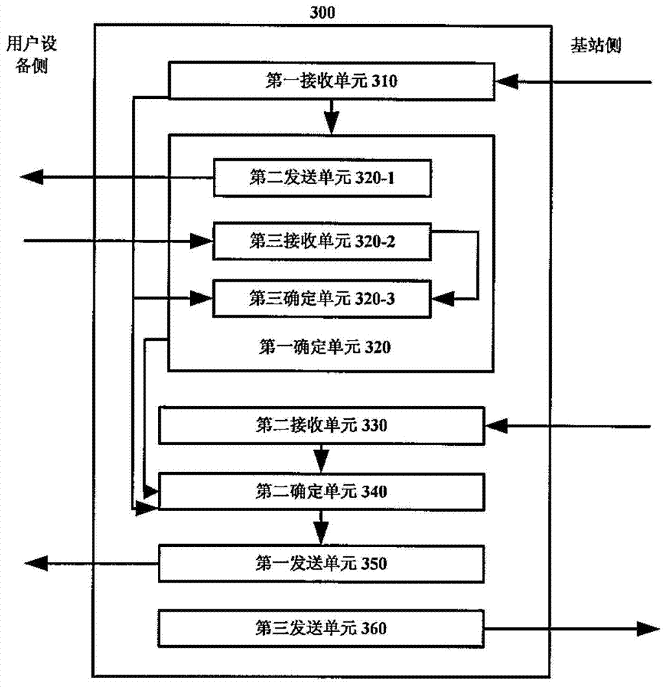

Image

  • Method and device for controlling user terminal uplink transmission power
  • Method and device for controlling user terminal uplink transmission power
  • Method and device for controlling user terminal uplink transmission power

Examples


Embodiment Construction

[0015] Embodiments of the present invention will be described in detail below with reference to the accompanying drawings.

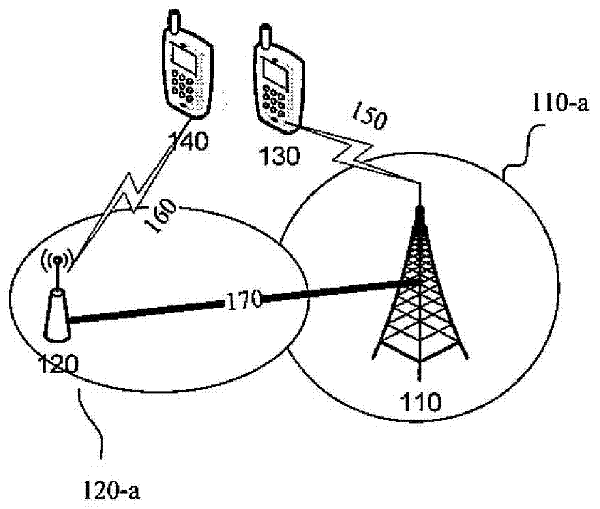
[0016] figure 1 A wireless communication system 100 in which the present invention may be implemented is schematically shown.

[0017] Such as figure 1 As shown, the wireless communication system 100 includes a first base station 110 corresponding to a first cell, a second base station 120 corresponding to a second cell, and user terminals 130 and 140 .

[0018] The first base station 110 provides a first coverage area 110-a and the second base station 120 provides a second coverage area 120-a.

[0019] Here, it is assumed that the user terminal 130 is within the first coverage area 110-a. Accordingly, the user terminal 130 communicates with the first base station 110 via the wireless link 150 . The user terminal 140 is within the second coverage area 120-a. Accordingly, the user terminal 140 communicates with the second base station 120 via the wir...


PUM


Abstract

The present invention proposes a device for controlling uplink transmission power of a user terminal. The method includes: receiving adjacent cell target interference and thermal noise IoT levels from adjacent cells; determining path losses from user terminals in the serving cell to the serving cell and adjacent cells; receiving IoT correction indicators from adjacent cells; considering user terminal The path loss to the adjacent cell, the IoT correction indicator received from the adjacent cell, the target IoT level of the adjacent cell, determine the uplink transmission power of the user terminal; and send the determined uplink transmission power of the user terminal to the user terminal. According to the present invention, the IoT level of each cell can be correctly controlled, and the avalanche problem of closed-loop uplink transmission power control can be avoided.

Description

technical field [0001] The present invention relates to the communication field, and more specifically, the present invention relates to a method and device for controlling uplink transmission power of a user terminal. Background technique [0002] In a cellular wireless communication system, inter-cell interference exists between a serving cell of a user terminal and an adjacent cell. In order to control the inter-cell interference, the most important mechanism is to control the uplink transmission power of the user terminal, so as to ensure that the serving cell of the user terminal can have the desired signal-to-interference-plus-noise ratio (SINR). Neighboring cells have minimal interference. Generally, the uplink transmission power of a user terminal in a cell is based on the path loss from the user terminal to its serving cell, the target interference and thermal noise IoT (Interference over Thermal) operating point of its serving cell, and the The target SINR is det...

Claims


Application Information

Patent Timeline
Patent Type & Authority Patents(China)
IPC IPC(8): H04W52/14H04W52/24
Inventor 刘建国刘瑾
Owner ALCATEL LUCENT SHANGHAI BELL CO LTD
Learn More