Oscillating bar bearing structure of arc trimmer

A technology of arc dresser and support structure, which is applied to the parts of grinding machine tools, abrasive surface adjustment devices, metal processing equipment, etc., and can solve the problems of high manufacturing cost, deviation of diamond pen movement trajectory, and high processing accuracy requirements. To achieve the effect of low manufacturing cost

Inactive Publication Date: 2014-11-19
WUXI MACHINETOOL
View PDF7 Cites 0 Cited by
  • Summary
  • Abstract
  • Description
  • Claims
  • Application Information

AI Technical Summary

Problems solved by technology

[0002] A diamond pen is arranged in the middle of the swing rod of the existing arc dresser, and the upper and lower ends of the swing rod are respectively supported in the corresponding bearing installation cavity through bearings. The upper bearing and the lower bearing need to be on the same axis. When the upper bearing and the lower bearing are not on the same axis, the movement track of the diamond pen in the middle of the swing rod will deviate, resulting in defective products of the grinding wheel to be dressed. Therefore, the machining accuracy of the bearing installation cavity of the dresser base is required to be high , so that the processing cost of the arc dresser is high, and the manufacturing cost is high

Method used


Image

  • Oscillating bar bearing structure of arc trimmer
  • Oscillating bar bearing structure of arc trimmer
  • Oscillating bar bearing structure of arc trimmer

Examples


Embodiment Construction

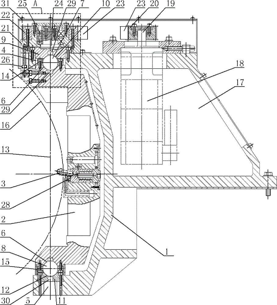
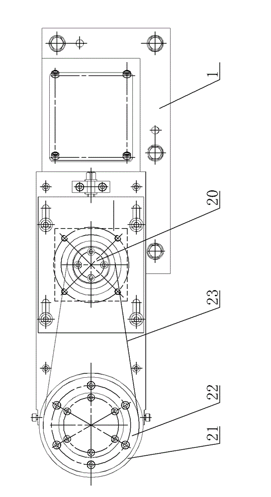
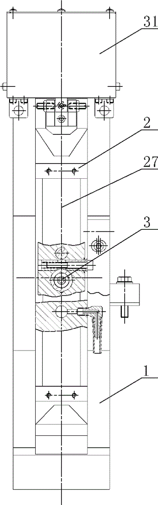
[0018] A swing rod support structure of a circular arc trimmer, see Figure 1 ~ Figure 4 : It includes a dresser base 1, a swing rod 2, and a diamond pen 3. The middle position of the swing rod 2 is arranged with a diamond pen 3. The upper end and the lower end of the swing rod 2 are respectively located in the corresponding upper end installation cavity of the dresser base 1. 4. The cavity 5 is installed at the lower end, and the protruding positions of the upper end and the lower end of the pendulum 2 are respectively provided with a conical frustum hole 6 with an inner concave end, and a steel ball structure is arranged in the conical frustum hole 6, and the steel ball structure specifically includes the upper end steel ball 7. The steel ball 8 at the lower end, the outer ring part of the upper gland 9 is fastened to the upper wall of the upper installation cavity 4 of the trimmer base 1, and the lower center of the upper gland 9 is provided with a concave conical upper hole...


PUM


Abstract

The invention provides an oscillating bar bearing structure of an arc trimmer. By means of the oscillating bar bearing structure, the upper end and the lower end of an oscillating bar can be on the same vertical axis, so that machining precision of a trimmer base cannot influence movement trails of a diamond pen and the manufacturing cost of the arc trimmer is low. The oscillating bar bearing structure comprises the trimmer base, the oscillating bar and the diamond pen, the middle of the oscillating bar is provided with the diamond pen, and the upper end and the lower end of the oscillating bar are located an upper end installation cavity and a lower end installation cavity of the trimmer base respectively. The oscillating bar bearing structure is characterized in that the convex position of the upper end and the convex position of the lower end of the oscillating bar are respectively provided with a cone frustum hole with inwards concave closing-in port, a steel ball structure is distributed in the cone frustum hole and comprises an upper steel ball and a lower end steel ball, the outer ring portion of an upper gland is fixedly connected with the upper wall of the upper end installation cavity of the trimmer base, and the center of the lower portion of the upper gland is provided with a cone frustum upper hole with an inward concave closing-in port.

Description

technical field [0001] The invention relates to the structural technical field of an arc trimmer, in particular to a swing rod support structure of an arc trimmer. Background technique [0002] A diamond pen is arranged in the middle of the swing rod of the existing arc dresser, and the upper and lower ends of the swing rod are respectively supported in the corresponding bearing installation cavity through bearings. The upper bearing and the lower bearing need to be on the same axis. When the upper bearing and the lower bearing are not on the same axis, the movement track of the diamond pen in the middle of the swing rod will deviate, resulting in defective products of the grinding wheel to be dressed. Therefore, the machining accuracy of the bearing installation cavity of the dresser base is required to be high , so that the machining cost and manufacturing cost of the arc dresser are high. Contents of the invention [0003] In view of the above problems, the present inv...

Claims


Application Information

Patent Timeline
Patent Type & Authority Applications(China)
IPC IPC(8): B24B53/06
CPCB24B53/12
Inventor 陈国华
Owner WUXI MACHINETOOL
Why Eureka
Try Eureka