Toothpaste extruder

An extruder and toothpaste technology, applied in the field of daily necessities, can solve the problems of waste of living cost, laboriousness in extruding toothpaste, inconvenient use of the toothpaste extruder, etc., and achieve the effect of saving energy and reducing living costs.

Active Publication Date: 2014-11-19
菏泽建数智能科技有限公司
View PDF6 Cites 11 Cited by
  • Summary
  • Abstract
  • Description
  • Claims
  • Application Information

AI Technical Summary

Problems solved by technology

[0002] There are many existing toothpaste extruders, but they cannot squeeze out the right amount of toothpaste, and the extrusion is not clean, resulting in a waste of living costs
In addition, some toothpaste extruders are inconvenient to use. The toothpaste shell is soft and easy to deform, so it is more laborious to squeeze out the toothpaste.

Method used


Image

  • Toothpaste extruder
  • Toothpaste extruder
  • Toothpaste extruder

Examples


Embodiment 1

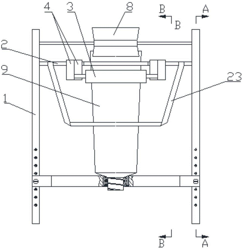
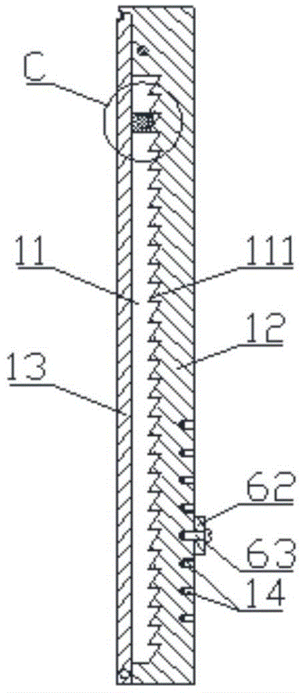
[0026] refer to Figure 1 to Figure 4 , a toothpaste extruder, including a bracket and extrusion parts, the bracket includes vertical plates 1 on both sides, and a first fixing member for fixing the head of the toothpaste case 9 is arranged between the vertical plates 1 on both sides and the second fixing part for fixing the tail of the toothpaste case 9, the extruding part is arranged between the first fixing part and the second fixing part, and the extruding part comprises a connecting rod 2 and an extruding part The roller 3 is provided with a chute 11 on the opposite side of the vertical plate 1 on both sides, the chute 11 extends from one end of the vertical plate 1 to the other end of the vertical plate and the two ends of the chute are closed, The connecting rod 2 is arranged in the chute and can slide along the chute from the tail of the toothpaste case to the head of the toothpaste case; the front and back of the toothpaste case are provided with the squeeze rollers ...

Embodiment 2

[0036] refer to Figure 9 The difference between this embodiment and the above-mentioned embodiment 1 is that two connecting rods are provided, and the two connecting rods are respectively distributed on both sides of the squeeze roller, and one end of the connecting rod is connected to the squeeze roller. connected, and the other end is inserted into the chute. All the other implementations are the same as in Example 1.

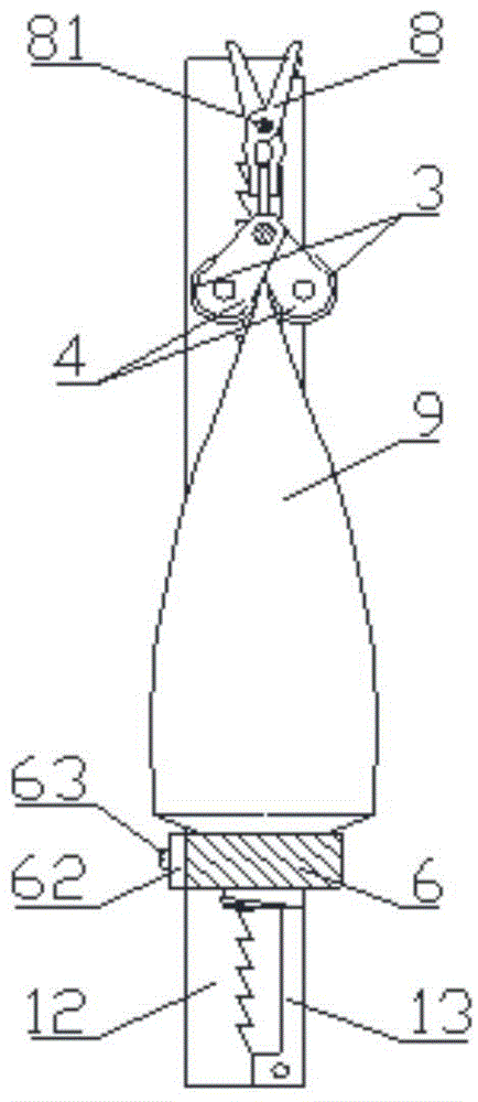
[0037] The present invention is generally erect when in use, as Figure 9 As shown, fixing seats 15 can be set at the bottoms of the two vertical plates, which is also convenient for pulling or pressing the connecting rod downwards, and will not retreat upwards.

[0038] In the above-mentioned embodiment 1 and embodiment 2, in order to facilitate the balance of force on the connecting rod, a drawstring 23 can be provided on the connecting rod, and the two ends of the drawstring are arranged close to the two ends of the connecting rod and connected with the...


PUM


Abstract

The invention discloses a toothpaste extruder. The toothpaste extruder comprises a support and an extruding component, wherein the support comprises vertical plates on two sides; a first fixing piece and a second fixing piece are arranged between the vertical plates on the two sides of the support; the first fixing piece is used for fixing the head of a toothpaste shell; the second fixing piece is used for fixing the tail of the toothpaste shell; the extruding component is arranged between the first fixing piece and the second fixing piece and comprises a connecting rod and extruding rolls; chutes are respectively formed in opposite side surfaces of the vertical plates on the two sides of the support; each chute extends from one end of the corresponding vertical plate to the other end of the corresponding vertical plate; two ends of each chute are closed; the connecting rod is arranged in the chutes and can slide along the chutes from the tail of the toothpaste shell to the head of the toothpaste shell; the extruding rolls are respectively arranged on the front surface and the reverse surface of the toothpaste shell and are parallel to each other; the axial direction of the toothpaste rolls is parallel to the axial direction of the connecting rod; and connecting pieces are respectively arranged at two ends of each extruding roll and are connected with the connecting rod.

Description

technical field [0001] The invention relates to a toothpaste extruder, which belongs to daily necessities. Background technique [0002] There are many existing toothpaste extruders, but they cannot extrude an appropriate amount of toothpaste, and the extrusion is not clean, resulting in waste of living costs. In addition, some toothpaste extruders are inconvenient to use. The toothpaste shell is soft and easy to deform, so it is more laborious to squeeze out toothpaste. Contents of the invention [0003] In order to overcome the above-mentioned shortcomings of existing toothpaste extruders, the present invention provides a toothpaste extruder with simple structure, stable and fixed toothpaste shell, convenient, labor-saving and sufficient extrusion of toothpaste, and saving living costs. [0004] The technical scheme adopted in the present invention is: [0005] The toothpaste extruder includes a bracket and an extruding part. The bracket includes vertical plates on bot...

Claims


Application Information

Patent Timeline
Patent Type & Authority Applications(China)
IPC IPC(8): B65B69/00
Inventor 陈滨王东张振兴
Owner 菏泽建数智能科技有限公司
Why Eureka
Try Eureka