End-expanded anchor rod and construction method thereof
A technology of anchor rod and body shape, which is applied in the direction of excavation, foundation structure engineering, sheet pile wall, etc., and can solve the problems of low pull-out force, poor gripping force between anchor body and anchor body, and small contact area between cement and anchor body and other problems, to achieve the effect of strengthening extrusion and expansion, good mechanical properties and strengthening strength
- Summary
- Abstract
- Description
- Claims
- Application Information
AI Technical Summary
Problems solved by technology
Method used
Image
Examples
Embodiment 1
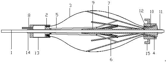
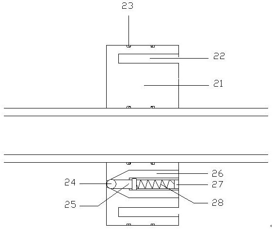
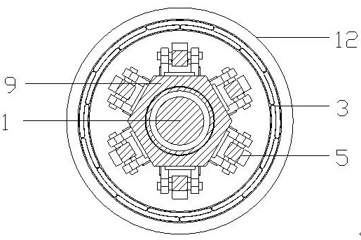
[0038] Such as Figure 1~6 As shown, an end-expanded body anchor 1 is characterized in that it includes an anchor body 1, a No. 1 pressing mechanism 2, a capsule body 3, a locking plug 4, a No. 1 support rod 5, and a No. 2 support rod 6 , No. 3 support rod 7, grouting pipe 8, sleeve pipe 9, slurry discharge channel 10, end plate 11, No. 2 pressing mechanism 12, sliding sleeve 13, smooth pipe 14, jacking plate 15; the No. 1 The compression mechanism 2 includes a mechanism main body 21, a locking buckle 22, a sealing rubber ring 23, a ball valve 24, a support guide frame 25, a grouting channel 26, a compression plug 27, and a compression spring 28; There is a smooth tube 14, and the smooth tube 14 and the sliding sleeve 13 are connected by welding. The No. 2 pressing mechanism 12 includes a mechanism main body 21, a locking buckle 22, a slurry discharge channel 10, and an occlusal cavity. The slurry pipe 8 passes through the sliding sleeve 13 and is welded on the sliding sleeve...
Embodiment 2
[0047] Such as Figure 1~6 As shown, a construction method of an end-expanded body anchor 1 is characterized in that a kind of end-expanded body-expanded anchor 1 is used for construction, and the specific construction steps are as follows:
[0048] Step 1: Pre-test;
[0049] First, a pre-test is carried out on the ground, and water is injected into the sliding sleeve 13 through the grouting pipe 8. The initial water injection pressure is 0.2MPa~0.5MPa, and the water injection pressure is gradually increased to 1.0MPa~2.0MPa for 1min~2min, increasing step by step. Increase the water injection pressure by 0.5MPa at each level, and last for 1min~2min at each level, record the critical water injection pressure when the capsule 3 just enters the water, until the capsule 3 is fully inflated, when the total flow of water in the slurry discharge channel 10 reaches When injecting 90% of the water flow rate, record the maximum water injection pressure Q when the capsule body 3 expands...
PUM
| Property | Measurement | Unit |
|---|---|---|
| Diameter | aaaaa | aaaaa |
| Diameter | aaaaa | aaaaa |
| Thickness | aaaaa | aaaaa |
Abstract
Description
Claims
Application Information
 - R&D
- Intellectual Property
- Life Sciences
- Materials
- Tech Scout
- Unparalleled Data Quality
- Higher Quality Content
- 60% Fewer Hallucinations
Browse by: Latest US Patents, China's latest patents, Technical Efficacy Thesaurus, Application Domain, Technology Topic, Popular Technical Reports.
© 2025 PatSnap. All rights reserved.Legal|Privacy policy|Modern Slavery Act Transparency Statement|Sitemap|About US| Contact US: help@patsnap.com


