
Photosensitive layer coating device

A technology of coating device and photosensitive layer, which is applied in the direction of device and coating for coating liquid on the surface, can solve the problems of easy slippage between roller and copper plate, inconsistent linear speed between roller and copper plate, uneven coating of photosensitive adhesive, etc. Achieve the effect of improving coating uniformity and avoiding external scattering

Active Publication Date: 2020-05-08
重庆市和鑫达电子有限公司
View PDF5 Cites 1 Cited by
  • Summary
  • Abstract
  • Description
  • Claims
  • Application Information

AI Technical Summary

Problems solved by technology

However, there are the following problems in the coating process: during the processing, the roller and the copper plate are easy to slip, which will cause the linear speed of the roller and the copper plate to be inconsistent, which will easily lead to uneven coating of the photosensitive adhesive

Method used


Image

  • Photosensitive layer coating device
  • Photosensitive layer coating device
  • Photosensitive layer coating device

Examples


Embodiment 1

[0026] Embodiment 1 is basically as follows:

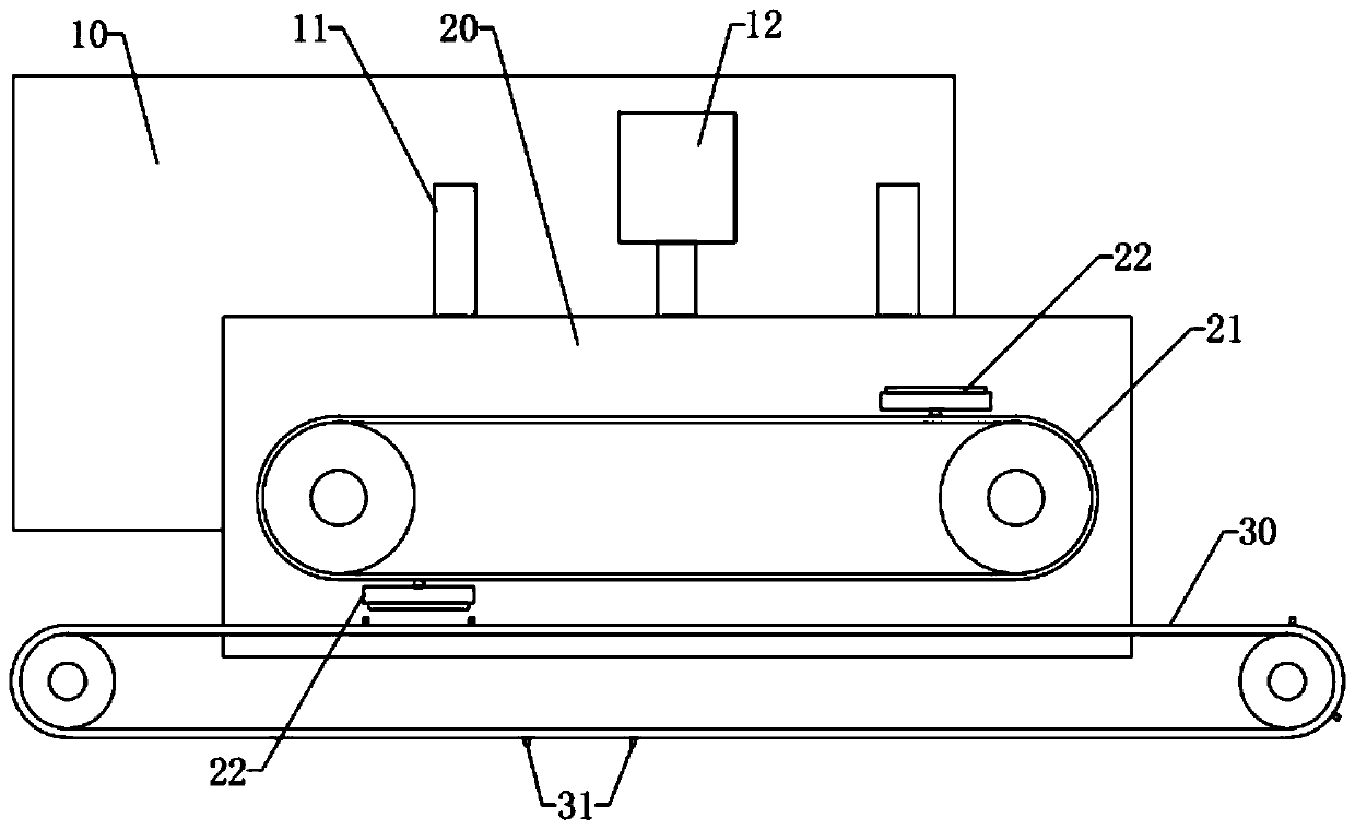
[0027] Apparatus for photosensitive layer coating, including frames, such as figure 1 As shown, a fixed plate 10 is fixed on the frame, and two vertical chutes 11 are provided on the fixed plate 10 , the chute 11 is slidably connected with a slider, and the slider is fixedly connected with a lifting plate 20 . The lifting plate 20 is rotatably connected with two sprockets, and the sprocket wheel on the right is connected with a driving motor, and the driving motor and the lifting plate 20 are fixed. The transmission chain 21 is connected on the two sprockets. The fixed plate 10 is fixedly connected with an air cylinder 12, and the telescopic shaft of the air cylinder 12 is fixed with the lifting plate 20.

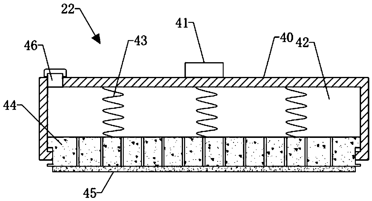
[0028] The conveyor chain 21 adopts a bent plate chain, and a plurality of coating assemblies 22 are fixed on the conveyor chain 21, and there are two coating assemblies 22 in this embodiment. The bottom of the transmission ...

Embodiment 2

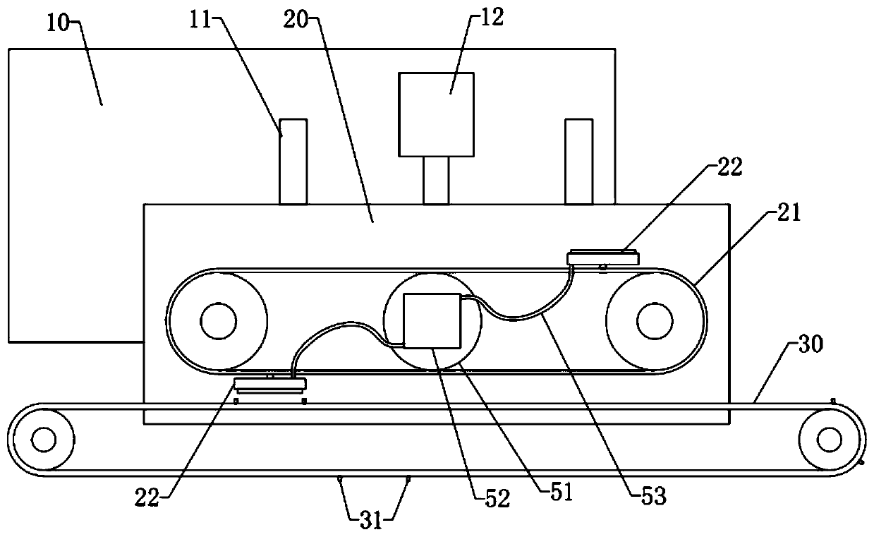
[0032] The difference from Embodiment 1 is that, as image 3 As mentioned above, a driven sprocket 51 is arranged between the left and right sprockets of the transmission chain 21 , and the diameter of the driven sprocket 51 is the same as that of the left and right sprockets, and the driven sprocket 51 meshes with the transmission chain 21 . The driven sprocket 51 is rotatably connected with the lifting plate 20 . A liquid storage tank 52 is fixed on the driven sprocket 51, and the liquid storage tank 52 is connected with a liquid delivery pump, and the liquid storage tank 52 is communicated with a flexible liquid supply pipe 53, such as Figure 4 As shown, the liquid supply pipe 53 communicates with the liquid filling port 46, and the liquid filling port 46 is fixed with a one-way liquid inlet valve.

[0033] In this way, when the photosensitive adhesive in the liquid storage chamber is almost used up, the liquid delivery pump can be opened to add the photosensitive adhesiv...


PUM


Abstract

The invention relates to the technical field of printed circuit board manufacturing equipment, in particular to a photosensitive layer coating device. The device comprises two conveying devices whichare arranged in an up-down mode and have the same linear speed, wherein one of the conveying devices conveys a circuit board, a plurality of coating assemblies are fixed to the other one conveying device, each coating assembly comprises a corresponding shell, a corresponding glue solution cavity is formed in each shell, the glue solution cavities are provided with openings capable of facing the circuit board correspondingly, pressing plates capable of being attached to the circuit board are slidably connected to the insides of the openings correspondingly, a plurality of pore channels enablingthe glue solution cavities to communicate with the outside are fully distributed in the pressing plates correspondingly, and elastic pieces capable of pushing the pressing plates to slide relative tothe openings are arranged between the pressing plates and the inner walls of the glue solution cavities correspondingly. According to the scheme, coating of photo-sensitive resist is completed by attaching the pressing plates to the surface of the circuit board, and the uniformity of coating of the photo-sensitive resist in the prior art is improved.

Description

technical field [0001] The invention relates to the technical field of printed circuit board manufacturing equipment, in particular to a photosensitive layer coating device. Background technique [0002] In the process of manufacturing printed circuit boards, it is necessary to coat the copper surface of the printed circuit board with photosensitive glue. The existing photosensitive glue is usually coated with rollers, and the copper plate is squeezed and clamped by two rollers. The copper plate, the copper plate and the roller move at the same linear speed, and the roller will coat the photosensitive adhesive on the surface of the copper plate during the transmission process. However, there are following problems in the coating process: in the process of processing, the roller and the copper plate tend to slip, which causes inconsistent linear speeds of the roller and the copper plate, which easily leads to uneven coating of the photosensitive adhesive. . Contents of the...

Claims


Application Information

Patent Timeline
Patent Type & Authority Applications(China)
IPC IPC(8): B05C1/02B05C11/10B05C11/11B05C13/02
CPCB05C1/025B05C11/10B05C11/1047B05C11/11B05C13/02
Inventor 胡荣华
Owner 重庆市和鑫达电子有限公司
Learn More