Combined shock absorption system of high-speed railway bridge and design method of combined shock absorption system

A shock absorbing system, high-speed railway technology, applied in bridge construction, bridges, bridge parts, etc., can solve the relative displacement of the pier beam without the introduction of the cable limiter, the lack of perfect design method for seismic design, and the difficulty of effectively controlling the relative displacement of the pier beam Displacement and other issues, to achieve the effect of easy control, ensuring earthquake resistance, and reducing earthquake force

Inactive Publication Date: 2014-11-19
DALIAN MARITIME UNIVERSITY
View PDF4 Cites 19 Cited by
  • Summary
  • Abstract
  • Description
  • Claims
  • Application Information

AI Technical Summary

Problems solved by technology

However, compared with highway bridges, high-speed railway bridges have much stricter control indicators for beam displacement. For high-speed railway bridges using anti-seismic rods, it is difficult to effectively control the relative displacement of pier beams under rare earthquakes due to the low stiffness of the anti-seismic rods after yielding. , especially under the action of near-fault ground motion with velocity pulse waveform (Wang Yan, Xie Xu, Shen Yonggang. Research on Seismic Response of Railway Shock-absorbing Bridges Under Near-field Earthquake[J]. Journal of Railway Science. 2012,34( 12):102-109.)
The current function-based seismic design lacks a comprehensive design method and does not introduce cable stoppers to control the relative displacement of pier beams

Method used


Image

  • Combined shock absorption system of high-speed railway bridge and design method of combined shock absorption system
  • Combined shock absorption system of high-speed railway bridge and design method of combined shock absorption system
  • Combined shock absorption system of high-speed railway bridge and design method of combined shock absorption system

Examples


Embodiment Construction

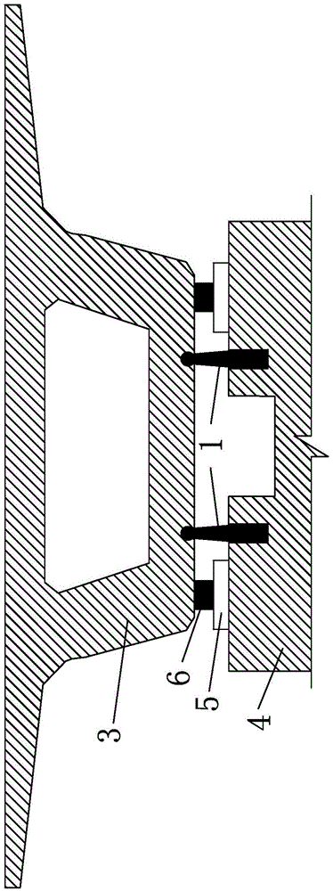
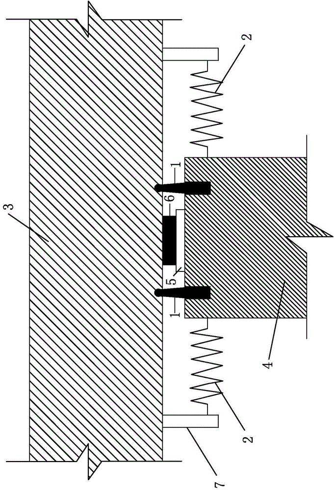
[0034] Such as figure 1 with figure 2 The shown a kind of high-speed railway bridge combined damping system comprises: bridge structure system and damping structure system; Wherein the bridge structure system comprises: girder 3, pier 4, be arranged on the pad stone 5 on the top of pier 4 and be arranged on pad The top of the stone 5 is used to support the bearing 6 of the main beam 3;

[0035] The shock-absorbing structure system includes anti-vibration rod 1 and cable limiter 2;

[0036] The anti-seismic rod 1 is made of low-yield steel and consists of an anchor section and a deformation section. The anchor section is anchored in the pier, and the end of the deformation section is spherical and extends into the main beam 3 to be hinged with the main beam 3;

[0037] The cable stopper 2 is to connect the steel strand between the main girder 3 and the pier 4, and a cable stopper 2 is respectively arranged on the left and right sides of the pier;

[0038] The above technica...


PUM


Abstract

The invention discloses a combined shock absorption system of a high-speed railway bridge and a design method of the combined shock absorption system. The combined shock absorption system is used for reducing and controlling damage to and destruction of the high-speed railway bridge in a strong earthquake. Firstly, a design scheme of a combined shock absorption and limiting system with earthquake-proof bars and cable limiters used is provided on the basis of a function separate support design concept, earthquake response of the bridge is reduced through yield energy consumption of the earthquake-proof bars, and the cable limiters are used for controlling oversize deformation of the earthquake-proof bars and preventing damage caused by bridge fall; secondly, in the framework of performance-based seismic design, design methods of the earthquake-proof bars and the cable limiters are provided under the conditions of frequent earthquakes, design earthquakes and rare occurrence earthquakes respectively; accordingly, the earthquake response of the high-speed railway bridge is reduced, the earthquake-proof property of the structure is improved, and the combined shock absorption system of the high-speed railway bridge and the design method of the combined shock absorption system are particularly suitable for bridge structures suffering from near-fault pulse-like ground motions.

Description

technical field [0001] The invention belongs to the technical field of bridge engineering, and relates to a combined damping system and its anti-seismic design method, more specifically, to a high-speed railway bridge combined damping system and its anti-seismic design method using anti-vibration rods and cable stoppers. design method. Background technique [0002] The operating mileage and construction scale of my country's high-speed railways rank among the top in the world, and are gradually extending to western provinces. The terrain in western my country is mostly mountainous, with strong neotectonic activity and extensive development of faults (fault zones). Large active faults can stretch for hundreds or even thousands of kilometers, with high seismic hazard. In the construction of high-speed railways, bridges account for a considerable proportion. In the west, it is inevitable that they are adjacent to or cross active faults. At the same time, there may be unexplore...

Claims


Application Information

Patent Timeline
Patent Type & Authority Applications(China)
IPC IPC(8): E01D19/04E01D19/00
Inventor 石岩王东升孙治国华承俊
Owner DALIAN MARITIME UNIVERSITY
Why Eureka
Try Eureka