Pneumatic Oil Limiting Device for Mixed Combustion Engine

An engine and oil-limiting technology, which is applied to combustion engines, internal combustion piston engines, engine components, etc., can solve problems such as difficult adjustment, high cost, and complicated installation, and achieve the effect of meeting economical operation

Inactive Publication Date: 2016-09-14
周继光
View PDF8 Cites 0 Cited by
  • Summary
  • Abstract
  • Description
  • Claims
  • Application Information

AI Technical Summary

Problems solved by technology

However, the components currently in use are basically complicated to install, difficult to adjust, and high in cost.

Method used


Image

  • Pneumatic Oil Limiting Device for Mixed Combustion Engine

Examples


Embodiment

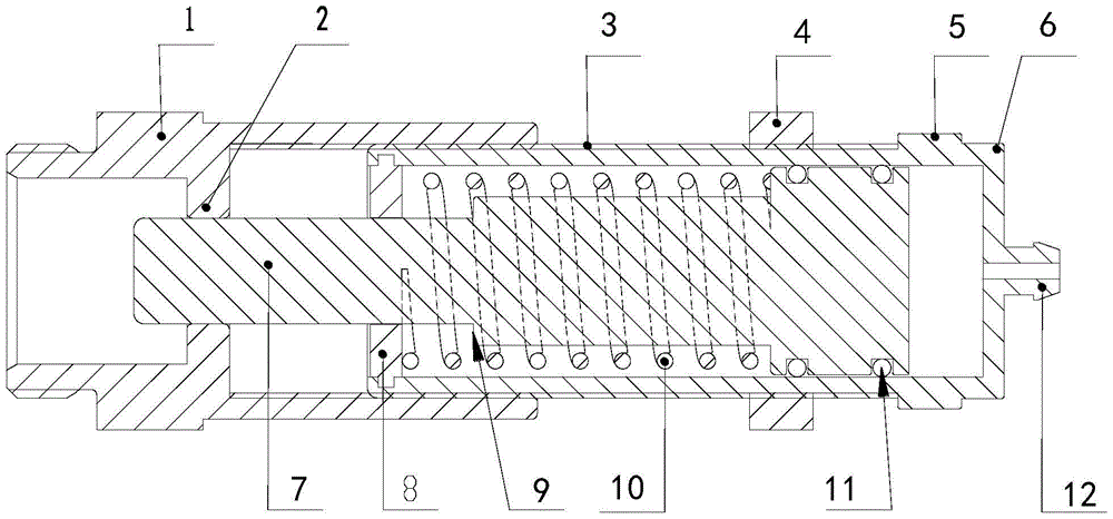
[0012] Such as figure 1 As shown, a pneumatic oil limiting device for a mixed-combustion engine includes a connecting seat 1 and a cylinder connected to the connecting seat 1; the cylinder includes a cylinder block 6 and a piston 7, and the cylinder block 6 is provided with a piston limit retaining ring 8, and the piston limit The function of the retaining ring 8 is to adjust the stroke of the piston 7 by cooperating with the limit step 9 on the piston rod. The outer wall of the cylinder body 6 is provided with an adjustment thread 3. The function of the adjustment thread 3 is to cooperate with the lock nut 4 to adjust the cylinder. The distance between the connecting seat 1 and the cylinder body 6 is provided with an air nozzle 12. The function of the air nozzle 12 is to realize the air intake inside the cylinder body to push the piston 7 to run. The piston rod of the piston 7 is provided with a limit step 9, and the piston 7 The piston rod located in the cylinder body 6 is p...


PUM


Abstract

The invention relates to a fuel supply limiter device for a diesel and natural gas mixed combustion engine, comprising a connecting seat and a cylinder connected to the connecting seat; There is an adjustment thread, an air nozzle is provided at one end of the cylinder body, and a limit step is provided on the piston rod of the piston. The other end is fixed on the piston; the connection seat is a through cavity, and a piston positioning hole for supporting the piston rod is provided inside it. One end of the connection seat is provided with an external thread to cooperate with the engine oil pump, and the other end is provided with a The internal thread is mated with the external thread on the outer wall of the cylinder. The invention is a device for limiting fuel supply of a diesel and natural gas engine. In the co-combustion mode, since the piston rod of the piston is provided with a limit step and a return spring, the stroke of the piston is effectively limited to meet the requirements of economical operation of the engine.

Description

technical field [0001] The invention relates to the field of a mechanical compression ignition type engine oil supply limiting device, in particular to a fuel supply limiter for a diesel and natural gas mixed combustion engine. Background technique [0002] In recent years, the engine control technology of diesel and natural gas mixed combustion has become more and more mature. During the operation of this kind of engine, precise air supply control is particularly important. At present, a real-time fuel consumption is the main control parameter, and it is used to supply air to the diesel and natural gas mixed combustion engine. Stable, but in the use of engines with mechanical fuel pumps, it is easy to cause excessive oil supply and excessive gas distribution to the engine, which will cause fuel waste and even damage the engine. In the prior art, in order to ensure that the fuel supply of the engine is not greater than the required value in the co-combustion mode, oil limita...

Claims


Application Information

Patent Timeline
Patent Type & Authority Patents(China)
IPC IPC(8): F02D19/08F02M37/06F02B69/04
Inventor 周继光邹晓明
Owner 周继光
Why Eureka
Try Eureka