Flow control joint and air inlet valve of scroll type air compressor

A flow control and hole control technology, which is used in rotary piston/swing piston pump components, mechanical equipment, machines/engines, etc. The effect of fast gas loading, high gas pressure and high flow rate

Inactive Publication Date: 2014-11-19
JIANGSU SUBA MACHINERY
View PDF4 Cites 0 Cited by
  • Summary
  • Abstract
  • Description
  • Claims
  • Application Information

AI Technical Summary

Problems solved by technology

However, because the diameter of the flow control hole is too large, the effect of pressure generation is not good.

Method used


Image

  • Flow control joint and air inlet valve of scroll type air compressor
  • Flow control joint and air inlet valve of scroll type air compressor
  • Flow control joint and air inlet valve of scroll type air compressor

Examples


Embodiment Construction

[0024] In order to make the above objects, features and advantages of the present invention more comprehensible, the present invention will be further described in detail below in conjunction with specific embodiments.

[0025] First of all, "one embodiment" or "embodiment" referred to herein refers to a specific feature, structure or characteristic that may be included in at least one implementation of the present invention. "In one embodiment" appearing in different places in this specification does not all refer to the same embodiment, nor is it a separate or selective embodiment that is mutually exclusive with other embodiments.

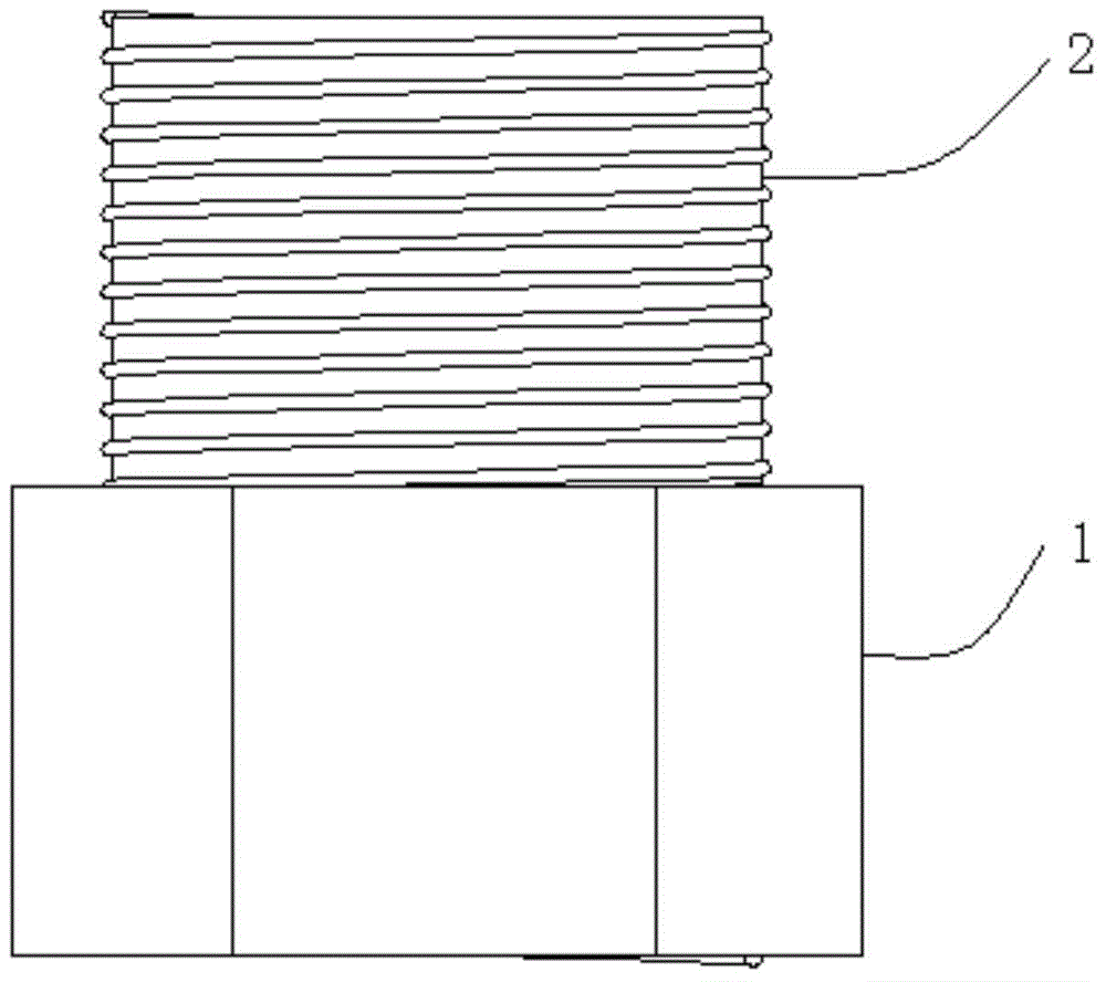
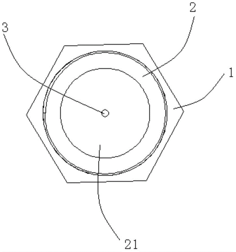
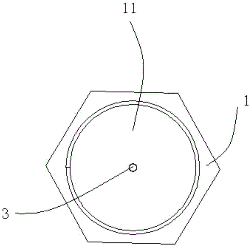
[0026] Secondly, the present invention is described in detail by using structural schematic diagrams, etc. When describing the embodiments of the present invention in detail, for the convenience of explanation, the schematic diagrams showing the flow control joints will not be partially enlarged according to the general scale, and the schematic di...


PUM


Abstract

The invention provides a flow control joint. The flow control joint comprises a first main body, a second main body and a control hole, wherein a first blind hole is formed in the first main body; one side of the first main body extends outwards to form the second main body; the second main body is provided with a second blind hole; the control hole is positioned between the first blind hole and the second blind hole and communicated to the second blind hole from the first blind hole. One flow control joint is arranged at each of an oil return inlet and an oil return outlet of a gas inlet valve; an oil return pipe is arranged at the joint of the flow control joint and an oil-gas tank and is directly communicated with the oil-gas tank. The gas generated by the flow control joint is high in pressure, high in flow and high in gas rising speed.

Description

technical field [0001] The invention relates to a flow control device, in particular to a flow control joint and a scroll air compressor inlet valve. Background technique [0002] The existing oil return pipe is directly connected to the oil and gas tank, or a flow control hole with a diameter slightly smaller than that of the oil return pipe is provided at the part connected to the oil and gas tank. Although the flow control hole will generate a certain gas pressure, the speed of the upper gas get faster. However, because the diameter of the flow control hole is too large, the effect of pressure generation is not good. [0003] Therefore, further improvements must be made to the prior art. Contents of the invention [0004] The technical problem to be solved by the present invention is to provide a flow control joint that overcomes the above defects, which can increase the gas pressure and increase the gas feeding speed. [0005] In order to solve the above technical p...

Claims


Application Information

Patent Timeline
Patent Type & Authority Applications(China)
IPC IPC(8): F04C29/12F04C28/24
Inventor 沈诠庭
Owner JIANGSU SUBA MACHINERY
Why Eureka
Try Eureka