Converted wave anisotropy velocity analysis method and device

An anisotropic and converted wave technology, applied in the field of anisotropic velocity analysis methods and devices for converted waves, can solve the problems of cumbersome process, complicated realization process, and difficult to determine, etc.

Active Publication Date: 2014-11-19
BC P INC CHINA NAT PETROLEUM CORP +1
View PDF6 Cites 24 Cited by
  • Summary
  • Abstract
  • Description
  • Claims
  • Application Information

AI Technical Summary

Problems solved by technology

[0003] The realization of the multi-parameter stacking velocity model mainly includes: the stacking velocity analysis stage and the pre-stack time migration stage, both of which require multiple iterative analysis, and multiple parameter values ​​(3 or 4), until the event is completely flattened. Therefore, the operation process is cumbersome, the implementation process is complicated, the workload is large, and the interaction between several parameter values ​​is difficult to determine accurately, which increases the processing cost and processing difficulty.
[0004] At present, some people have used the two-parameter simplified dynamic correction equation to analyze the superposition velocity of converted waves, which simplifies the operation process and computational complexity to a certain extent. However, the converted wave prestack time migration still needs to determine the converted wave velocity at the same time. (V c ), vertical velocity ratio (γ 0 ), effective speed ratio (γ eff ) and converted wave equivalent anisotropy (χ eff ) these four parameters are still relatively cumbersome to implement, that is, the implementation process of converted wave prestack time migration velocity analysis is still very complicated

Method used


Image

  • Converted wave anisotropy velocity analysis method and device
  • Converted wave anisotropy velocity analysis method and device
  • Converted wave anisotropy velocity analysis method and device

Examples


Embodiment Construction

[0075] In order to make the object, technical solution and advantages of the present invention clearer, the present invention will be described in further detail below in conjunction with the embodiments and accompanying drawings. Here, the exemplary embodiments and descriptions of the present invention are used to explain the present invention, but not to limit the present invention.

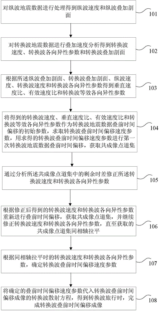
[0076] In an embodiment of the present invention, a converted wave anisotropy velocity analysis method is provided, such as figure 1 shown, including the following steps:

[0077] Step 101: Process the P-wave seismic data to obtain P-wave velocity and P-wave stacked section;

[0078] Step 102: Perform stacking velocity analysis on the converted wave seismic data to obtain converted wave velocity, converted wave anisotropy parameters and converted wave stacking section;

[0079] Step 103: Obtain the vertical velocity ratio, effective velocity ratio, and converted wave equivalent anisotropy par...


PUM


Abstract

The invention provides a converted wave anisotropy velocity analysis method and device. The method includes the steps that the vertical velocity ratio, the effective velocity ratio and equivalent anisotropy parameters of converted waves are worked out according to the stacked section of longitudinal waves, the stacked section of the converted waves, the velocity of the longitudinal waves, the velocity of the converted waves and anisotropy parameters of the converted waves; with the speed of the converted waves, the vertical velocity ratio, the effective velocity ratio and the equivalent anisotropy parameters of the converted waves which are obtained as the initial parameters of pre-stack time migration of seismic data of the converted waves, the velocity parameter of pre-stack time migration of the converted waves is worked out, the first time of pre-stack time migration is performed, and a common imaging point gather is acquired; by analyzing the velocity of the converted waves corrected by residual moveout and the anisotropy parameters of the converted waves in the common imaging point gather, the common imaging point gather is acquired, and the velocity of the converted waves and the anisotropy parameters of the converted waves continue to be corrected till the acquired common imaging point gather is in even alignment in window. Through the converted wave anisotropy velocity analysis method and device, the accuracy of the converted wave anisotropy velocity analysis result is improved, and the processing cost is reduced.

Description

technical field [0001] The invention relates to the technical field of converted wave seismic data processing, in particular to a converted wave anisotropic velocity analysis method and device. Background technique [0002] High-quality imaging processing of converted wave data is the key to the success of multicomponent seismic exploration. The converted wave prestack time migration imaging method based on multi-parameter velocity model can effectively avoid the problem of difficult extraction of co-conversion points, so that the imaging effect It has been obviously improved, and this method has achieved good application results in multi-component seismic exploration. This method is based on the converted wave velocity (V c ), vertical velocity ratio (γ 0 ), effective speed ratio (γ eff ) and converted wave equivalent anisotropy (χ eff ) based on multi-parameter velocity analysis, the model of stacking velocity analysis is used as the initial model of converted wave pre...

Claims


Application Information

Patent Timeline
Patent Type & Authority Applications(China)
IPC IPC(8): G01V1/30
Inventor 陈海峰李向阳蔡志光撒振宇宋建军
Owner BC P INC CHINA NAT PETROLEUM CORP
Why Eureka
Try Eureka