Cooling devices for rotors of electromechanical machines

A cooling device and mechanical technology, applied in cooling/ventilation devices, electromechanical devices, electric components, etc., can solve problems such as cost and achieve the effect of simple support and guidance

Active Publication Date: 2017-10-24
SIEMENS AG
View PDF5 Cites 0 Cited by
  • Summary
  • Abstract
  • Description
  • Claims
  • Application Information

AI Technical Summary

Problems solved by technology

Of course, the disadvantage here is that in such a cooling device that rotates with the shaft, complex seals must be provided in order to seal the cooling device accordingly.

Method used


Image

  • Cooling devices for rotors of electromechanical machines

Examples


Embodiment Construction

[0019] The following detailed examples are preferred embodiments of the present invention.

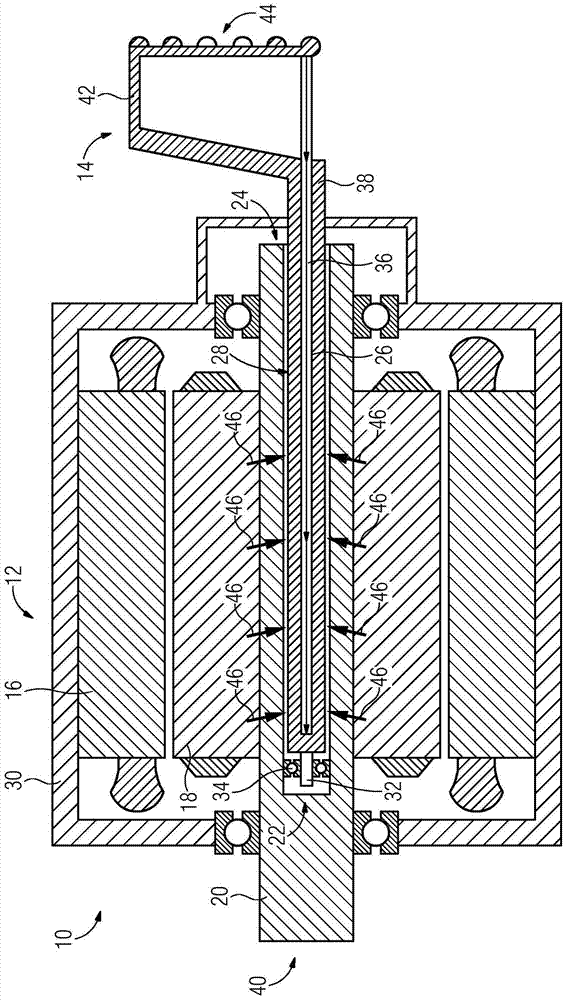
[0020] The drawing shows a sectional side view of the mechanical device 10 . The mechanical device 10 includes an electric machine 12 and a cooling member 14 described in more detail below.

[0021] The mechanical device 10 can be arranged, for example, in an electric vehicle for driving one or more drive wheels. In this case, the cooling component 14 can be associated with a cooling circuit of the electric vehicle. The cooling component 14 can also be associated with a cooling circuit of the electric machine 12 .

[0022] Electric machine 12 includes a stator 16 and a rotor 18 . The rotor 18 is mechanically connected to a shaft 20 . In this case, the shaft 20 includes a cutout 22 . The cutout 22 is preferably introduced as a bore into the shaft 20 from a first end side 24 thereof. In this case, the cutout 22 is designed as a blind hole which is inserted centrally into the shaft ...


PUM


Abstract

The invention relates to an electromechanical machine (12) having: a stator (16); a rotor (18); a shaft (20) mechanically connected to the rotor (18); and a cooling device (26), the The cooling device is arranged in the shaft (20), wherein the shaft (20) has a cutout (22), in which the cooling device (26) is arranged, wherein the shaft (20) is designed so that it can be arranged relative to the cooling device ( 26) Turn.

Description

technical field [0001] The invention relates to an electric machine having: a stator; a rotor; a shaft, which is mechanically connected to the rotor; and a cooling device, which is arranged in the shaft. The invention also relates to a mechanical device. Background technique [0002] During electromechanical operation, losses develop in the rotor due to ohmic resistance. This loss causes the rotor to heat up. This dissipated heat has to be dissipated outwards, since excessively high temperatures in the electric machine generally lead to lower efficiency or power limitations. Furthermore, electric machinery can be damaged due to overheating. [0003] In electromechanical machines according to the prior art, part of the heat loss flows outwards via the motor shaft. A disadvantage here is that, in particular, the inner ring of the ball bearing for supporting the rotor is heated. Another part of the lost heat is output via the air gap between the stator and the rotor to the...

Claims


Application Information

Patent Timeline
Patent Type & Authority Patents(China)
IPC IPC(8): H02K1/32H02K9/20H02K9/22
CPCH02K1/32H02K9/227H02K9/225
Inventor 诺贝特·韦纳
Owner SIEMENS AG
Why Eureka
Try Eureka