Step-by-step teaching robot based on motor power and control method thereof

A teaching robot and motor-assisted technology, applied in computer control, manipulator, program control, etc., can solve problems such as high requirements for detection systems and computing systems, lag, and inability to eliminate the movement resistance of multi-joint arms in time.

Active Publication Date: 2014-11-26
FOSHAN CLEV ROBOT
View PDF7 Cites 32 Cited by
  • Summary
  • Abstract
  • Description
  • Claims
  • Application Information

AI Technical Summary

Problems solved by technology

However, the scheme of detecting the position of the joint shaft at all times has high requirements on the detection system and the computing system; the use of an encoder to detect the direction o

Method used


Image

  • Step-by-step teaching robot based on motor power and control method thereof
  • Step-by-step teaching robot based on motor power and control method thereof
  • Step-by-step teaching robot based on motor power and control method thereof

Examples


Embodiment 1

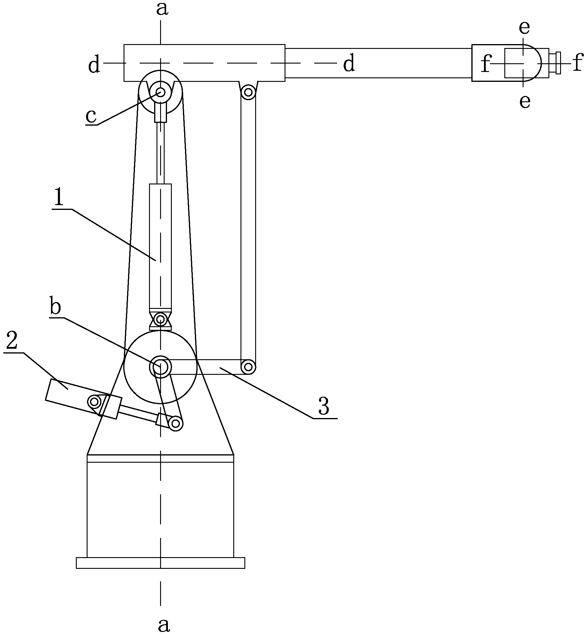
[0025] refer to figure 1 , the hand-held teaching robot based on motor assistance includes a large arm seat supported on the base that can rotate around the vertical axis a-a (J1 joint axis), supported on the large arm seat and can swing back and forth around the axis b (J2 joint axis) Boom, supported on the forearm seat that can swing up and down around the axis c (J3 joint axis), installed in the forearm seat, and can rotate around its axis d-d (J4 joint axis), installed at the end of the forearm The wrist swing section that can swing around the axis e-e (J5 joint axis) is installed on the wrist swing section that can rotate around the axis f-f (J6 joint axis) and is used for installing tools.

[0026] The first cylinder 1 is installed on the big arm seat, one end of which is hinged with the big arm seat, and one end of the piston rod is hinged with the supporting shaft of the small arm seat for the balance of the big arm. When the boom rotates to a certain position, the pu...

Embodiment 2

[0033] The magnitude of the assisting torque can be obtained through prior measurement. One of the measurement methods is, for a certain joint axis, apply different torques to the motor at a certain position, and it can be obtained that the joint axis is in the positive direction or the reverse direction at this position. The critical balance moment value just at rest is used as the positive or reverse assist torque value of the joint at this position. By measuring several positions in this way, a power-assisted calculation system associated with the pose of the multi-joint arm can be established. When teaching and controlling, the power-assisted torque required for the joint axis at a specific position can be obtained by searching and interpolating in the power-assisted calculation system. .

[0034] Taking the big arm as an example, although the function of being dragged and taught can be achieved through the balanced design, due to its heavy load, the frictional resistance ...

Embodiment 3

[0037] The balance state of the front-end joint axis is usually related to the posture of the rear-end joint. For example, the J5 joint axis will affect the J3 joint axis. When the influence is not large, it can be ignored for simplifying the processing, and it is enough to only deal with it according to the method of embodiment 1; when this influence needs to be considered, it is necessary to calibrate a certain position of the corresponding front joint axis when the rear joint axis is at The critical balance torque at different positions is obtained from a set of multivariate data. During the teaching control, the determined assist torque should be obtained according to the actual position data of the relevant joint axes.

[0038] Taking the J3 joint axis on the forearm as an example, considering the influence of the posture of the wrist swing segment on the forearm, the influence is more obvious when the load is large and the center of gravity is far away. The calibration met...


PUM


Abstract

The invention discloses a step-by-step teaching robot based on motor power. The step-by-step teaching robot comprises a base and a multi-joint arm connected with the base. The multi-joint arm is in transmission connection with a connecting joint of the base through a join shaft, and all joints of the multi-joint arm itself are all in transmission connection through joint shafts. The step-by-step teaching robot further comprises an encoder for detecting and recording the movement situations of the joint shafts, the joint shafts are connected with a motor, and the encoder is electrically connected with a control system. A power computing system is further arranged. A manipulation sensing mechanism is arranged at the tail end of the multi-joint arm, and the power computing system is electrically connected with the motor and the manipulation sensing mechanism. The invention further discloses a control method of the robot. According to the step-by-step teaching robot based on the motor power and the control method of the robot, the rotation directions of the joint shafts are determined through trigger signals on the manipulation sensing mechanism to enable the motor power torque providing process to be smooth and sensitive. The computing amount in signal processing is small, complex dynamics equations do not need to be solved, and therefore the requirement for the computing capacity of a CPU is greatly lowered. The step-by-step teaching robot based on the motor power and the control method of the step-by-step teaching robot can be used in the fields such as spray coating production lines.

Description

technical field [0001] The invention relates to a control method of an industrial robot, in particular to a motor-assisted hand-held teaching robot, and a control method of the above-mentioned hand-held teaching robot. Background technique [0002] For the hand-held teaching robot, whether the teaching is light or not is an important indicator to measure its practicality. Chinese patent document CN103425100A discloses a robot direct teaching control method based on torque balance. It detects the position of the joint axis at all times, provides the corresponding torque to ensure that the multi-joint arm of the robot is in a state of force balance, and uses an encoder to detect joints. The motor signal of the axis, so as to obtain the actual movement direction of each joint axis when the multi-joint arm moves. However, the solution to detect the position of the joint axis at all times has high requirements on the detection system and the computing system; the use of an encod...

Claims


Application Information

Patent Timeline
IPC IPC(8): B25J13/08B25J9/08B25J11/00G05B19/042
Inventor 倪立新刘达刘汝发
Owner FOSHAN CLEV ROBOT
Why Eureka
Try Eureka