
Logic control method for visual management of generator-transformer unit protection devices

A logic control, generator-transformer group technology, applied in data processing applications, instruments, information technology support systems, etc., can solve problems such as inability to truly restore, different sensitivity of operating equipment-related parameters, and many generator-transformer group protection devices, etc. Achieve the effect of avoiding protection from misoperation or refusal to move

Inactive Publication Date: 2014-11-26
陕煤电力信阳有限公司
View PDF3 Cites 1 Cited by
  • Summary
  • Abstract
  • Description
  • Claims
  • Application Information

AI Technical Summary

Problems solved by technology

[0002] At present, the protection devices of power plants (including self-provided power plants and substations) are set in independent rooms. Equipment maintenance personnel need to conduct on-site inspections once a day, and operating personnel need to conduct on-site inspections every two hours, so they cannot be monitored in real time. , Of course, it is impossible to detect hidden dangers in advance and eliminate potential risks
At the same time, due to the many protection devices and complex principles of the generator-transformer unit, and the technical level of the technicians is different, the sensitivity to the relevant parameters of the operating equipment is different, so that after a fault occurs, the process of the fault cannot be quickly, accurately and truly restored

Method used


Image

  • Logic control method for visual management of generator-transformer unit protection devices

Examples


Embodiment Construction

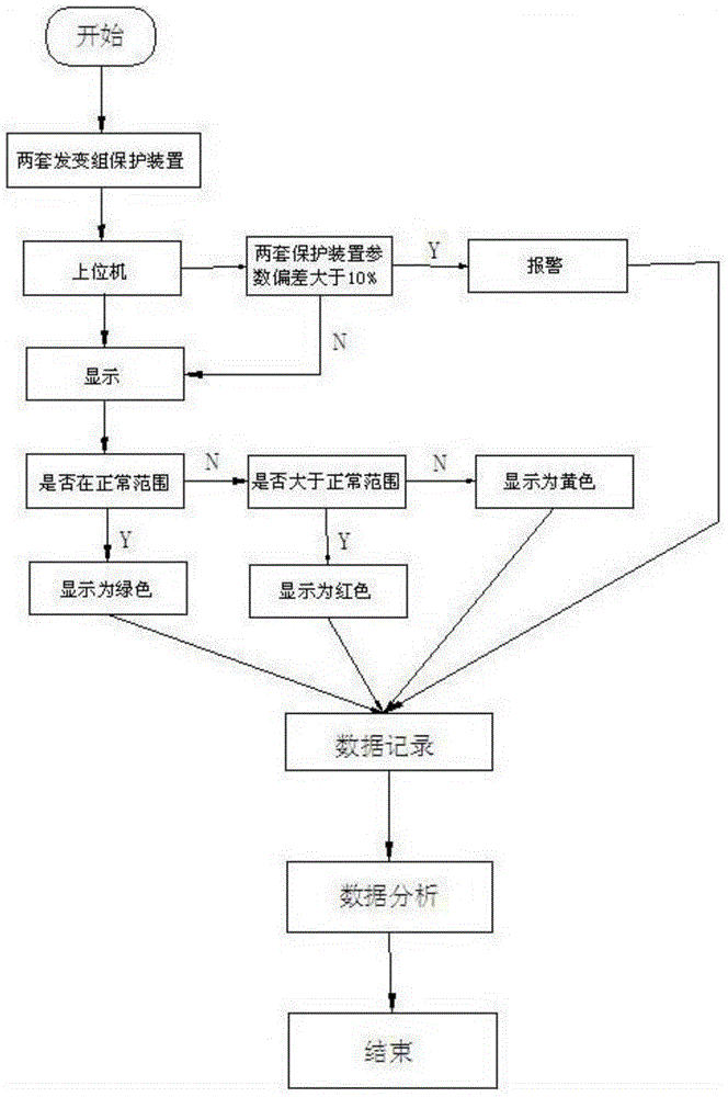
[0016] A protection logic control method for real-time monitoring of the generator-transformer group of the present invention can be implemented by computer software. The real-time data of the difference between the two sets of generator-transformer protection devices are transmitted to the host computer through the network. It can avoid the inconsistency of the technical level of the technicians and the sensitivity to the relevant parameters of the operating equipment; and after the equipment fails, it can accurately and truly restore the occurrence process of the failure. The method of the present invention mainly includes three major functional modules: 1) displaying real-time data, the present invention can display the real-time data of the difference between two sets of generator-transformer protection devices in real time; display the real-time status of each data in each protection logic condition. And through the three colors of yellow, green and red, when the differen...


PUM


Abstract

The invention relates to a real-time monitoring and managing method of protection devices of power systems, in particular to real-time monitoring and managing of generator-transformer unit protection devices of power stations, and discloses a logic control method for management of protection devices at the places such as self-generation power stations and transformer substations. The logic control method for visual management of the generator-transformer unit protection devices is characterized by comprising the following control steps that the difference of real-time operation data of the two generator-transformer unit protection devices is transmitted to an upper computer through a network; when the difference of the operation data exceeds 10%-15% of a protection action fixed value, namely, when the difference of the operation data is beyond the normal range, an alarm is given out; the data are displayed; the data are recorded; the data are analyzed; the whole procedure ends. The logic control method for visual management of the generator-transformer unit protection devices has the advantages that visualization of protection logic and real-time monitoring of relevant parameters are realized; when the difference is beyond the normal range of the protection action fixed value, the alarm is given out; real-time operation data are stored regularly, fault data are stored when a fault occurs, a report form can be formed by analyzing the real-time operation data, and the operation states of the protection devices can be judged easily; playback and simulation of the real-time operation data and the fault data are conducted, and fault analysis is facilitated.

Description

technical field [0001] The present invention relates to a method and device for real-time monitoring and management of protection devices in electric power systems, especially for real-time monitoring and management of protection devices for generating and transforming groups in power plants, and is also applicable to a logic control method and device for managing protection devices in self-provided power plants, substations, etc. . Background technique [0002] At present, the protection devices of power plants (including self-provided power plants and substations) are set in independent rooms. Equipment maintenance personnel need to conduct on-site inspections once a day, and operating personnel need to conduct on-site inspections every two hours, so they cannot be monitored in real time. , Of course, it is impossible to discover hidden dangers in advance and eliminate potential risks. At the same time, due to the many protection devices and complex principles of the gene...

Claims


Application Information

Patent Timeline
Patent Type & Authority Applications(China)
IPC IPC(8): G06Q50/06
CPCY04S10/50
Inventor 张松跃李振华唐志
Owner 陕煤电力信阳有限公司
Learn More