Antenna mount

A technology of mounting seat and antenna, applied in the direction of antenna support/installation device, etc., can solve the problems of affecting signal reception, easy shaking of the antenna, and inability to adjust the angle, so as to simplify the adjustment operation process, facilitate later adjustment and debugging, and improve the fixing effect. Effect

Inactive Publication Date: 2014-11-26
SUZHOU BIANTONG SENSING TECH
View PDF9 Cites 2 Cited by
  • Summary
  • Abstract
  • Description
  • Claims
  • Application Information

AI Technical Summary

Problems solved by technology

[0002] With the development of communication systems, antennas are used more and more widely, but because the antenna is easy to shake when it encounters vibration or wind, which affects the reception of signals, how to fix the antenna is a problem that needs to be solved. Device research is also becoming more and more important
[0003] At present, some antenna fixing devices have appeared to improve the stability of the antenna installation, but it still cannot completely avoid

Method used


Image

  • Antenna mount
  • Antenna mount

Examples


Example Embodiment

[0015] The specific embodiments of the present invention will be described below in conjunction with the drawings.

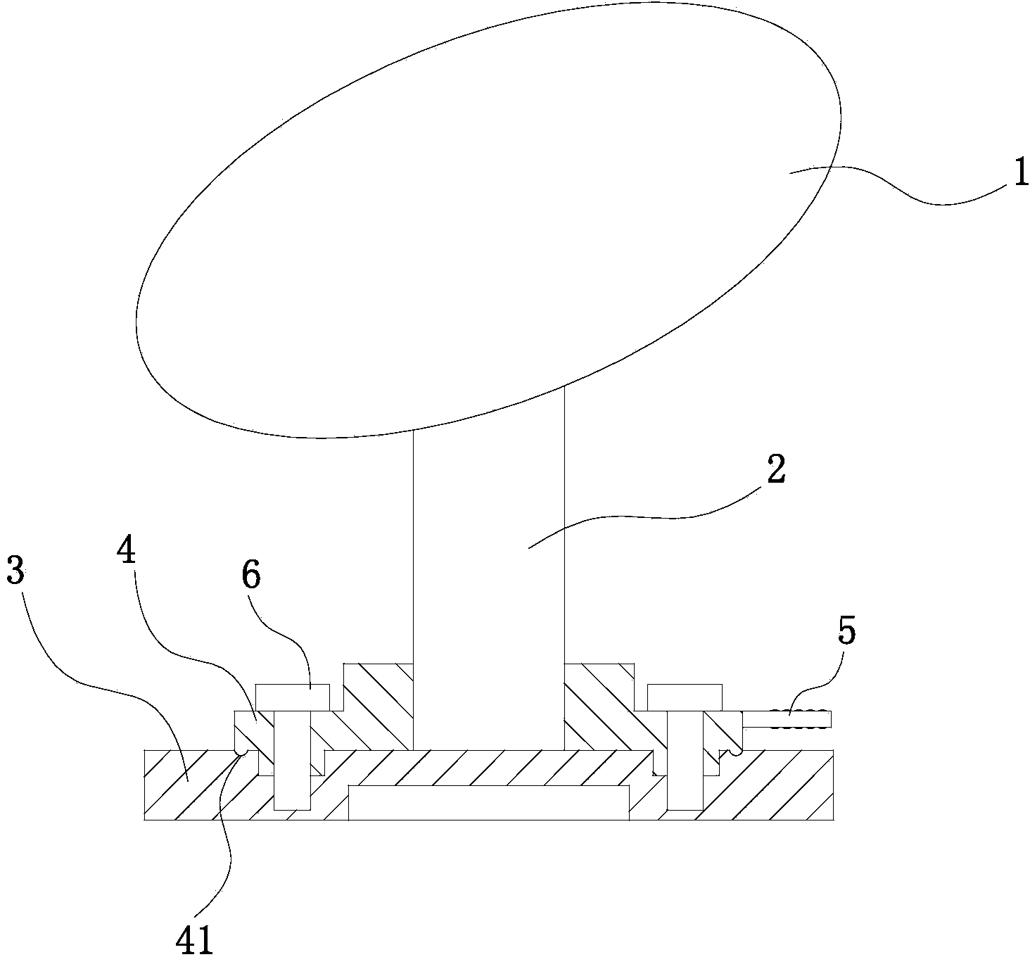
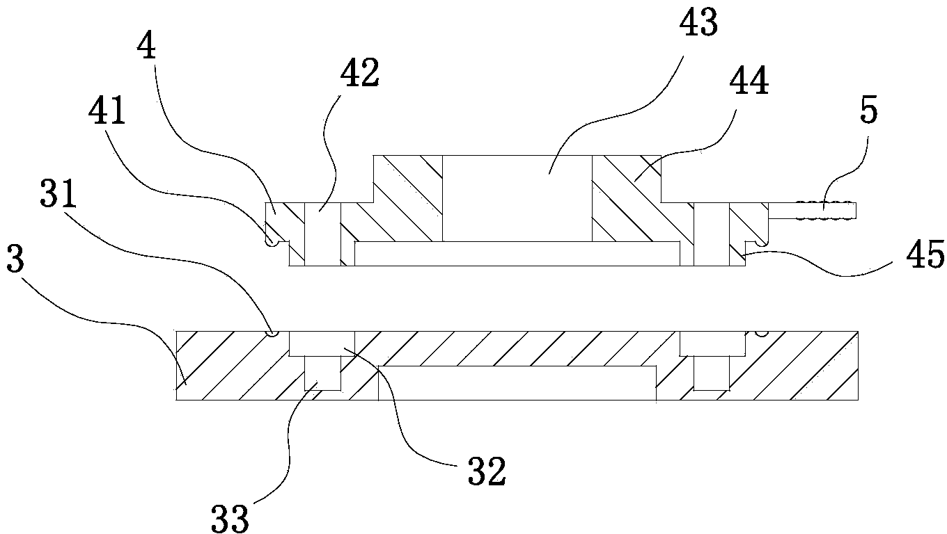
[0016] Such as figure 1 and figure 2 As shown, the antenna mounting base of this embodiment includes a base 3 on which a mounting rod 2 is fixed to the antenna 1. The upper surface of the base 3 is provided with a circular mounting groove 32, and the bottom surface of the circular mounting groove 32 is provided with An annular fixing groove 33, the base 3 fixes the base 4 through the annular mounting groove 32 and the annular fixing groove 33, the lower surface of the base 4 is provided with a mounting ring 45 installed in the annular mounting groove 32, and the mounting ring 45 has a mounting through hole 42. The mounting ring 45 rotates and adjusts the position in the annular mounting groove 32, and when the position is adjusted, it is fixed by the annular fixing groove 33 and the screw 6. For ease of installation, the width of the annular mounting groove 32 is ...


PUM


Abstract

The invention relates to an antenna mount which includes a pedestal. An installation rod of an antenna is fixedly connected with the pedestal. The upper surface of the pedestal is provided with annular installation grooves. The bottom faces of the annular installation grooves are provided with annular fixing grooves. The pedestal fixes a base through the annular installation grooves and the annular fixing grooves. The lower surface of the base is provided with installation rings which are arranged in the annular installation grooves. The installation rings are provided with installation through holes. The upper surface of the base is provided with a boss. The boss is provided with an installation hole for installing the installation rod. One side of the base is connected with an adjustment handle. The antenna mount is simple in structure and improves a fixing effect of the antenna through cooperative installation of the base and the pedestal and simplifies an adjustment operation process; and later adjustment and debugging are also facilitated.

Description

technical field [0001] The invention relates to the technical field of communication antennas, in particular to an antenna mounting base. Background technique [0002] With the development of communication systems, antennas are used more and more widely, but because the antenna is easy to shake when it encounters vibration or wind, which affects the reception of signals, how to fix the antenna is a problem that needs to be solved. Device research is also becoming more and more important. [0003] At present, some antenna fixing devices have appeared to improve the installation stability of the antenna, but it still cannot completely avoid the shaking of the antenna when it encounters strong wind and the slight change of position after a long time. After the antenna is fixed by the fixing device, the angle cannot be adjusted by itself, and only the installation rod of the antenna can be rotated to adjust the angle. From the current situation of rotating the installation rod,...

Claims


Application Information

Patent Timeline
IPC IPC(8): H01Q1/12
Inventor 不公告发明人
Owner SUZHOU BIANTONG SENSING TECH
Why Eureka
Try Eureka