Pressure compensation type emitter and drip irrigation belt/tube

A technology of pressure compensation and dripper, which is applied in the direction of spraying device, horticulture, botanical equipment and methods, etc., and can solve the problem of large change of dripper flow rate, etc.

Active Publication Date: 2014-12-03
SHENZHEN BATIAN ECOTYPIC ENG
View PDF5 Cites 3 Cited by
  • Summary
  • Abstract
  • Description
  • Claims
  • Application Information

AI Technical Summary

Problems solved by technology

[0004] Aiming at the deficiencies of the existing technology, the present invention proposes a pressure-compensated dripper and a drip irrigation belt/pipe, aiming to

Method used


Image

  • Pressure compensation type emitter and drip irrigation belt/tube
  • Pressure compensation type emitter and drip irrigation belt/tube
  • Pressure compensation type emitter and drip irrigation belt/tube

Examples


Embodiment Construction

[0023] In order to make the object, technical solution and advantages of the present invention clearer, the present invention will be further described in detail below in conjunction with the accompanying drawings and embodiments. It should be understood that the specific embodiments described here are only used to explain the present invention, not to limit the present invention.

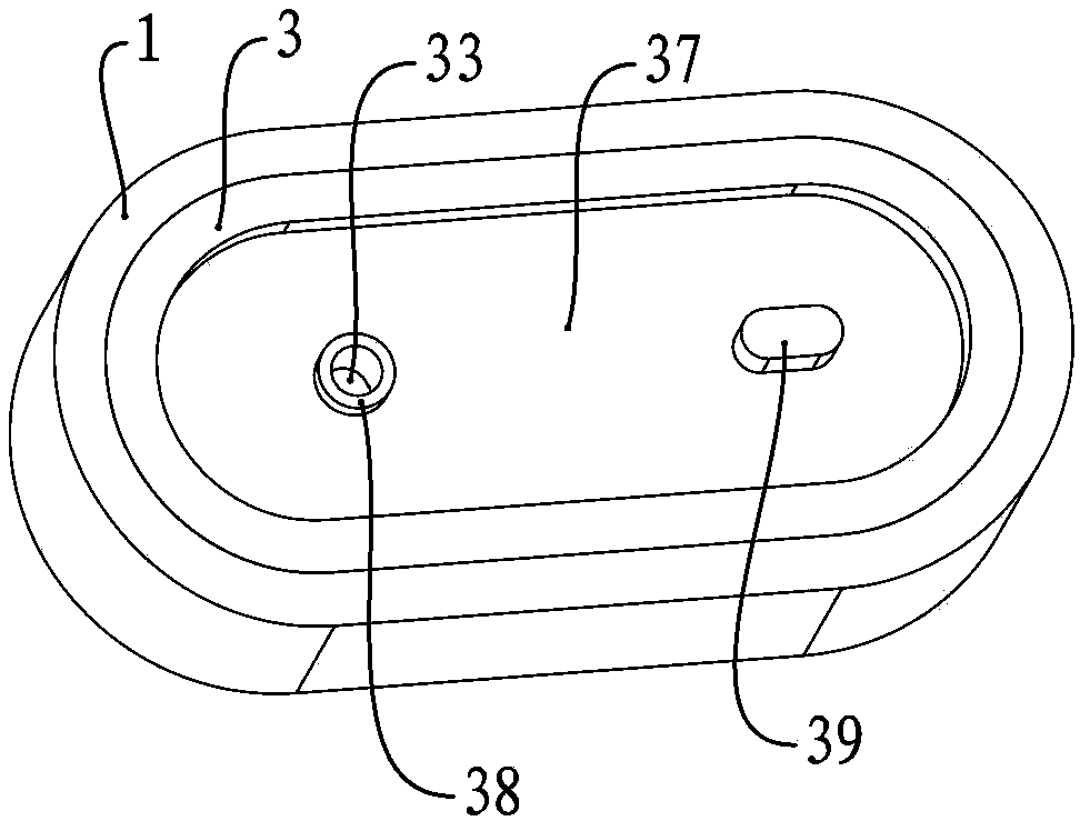
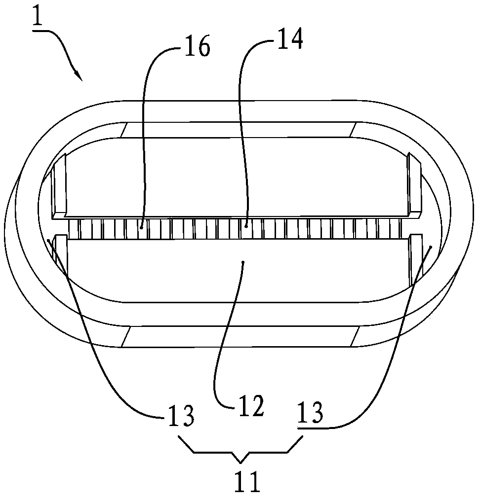
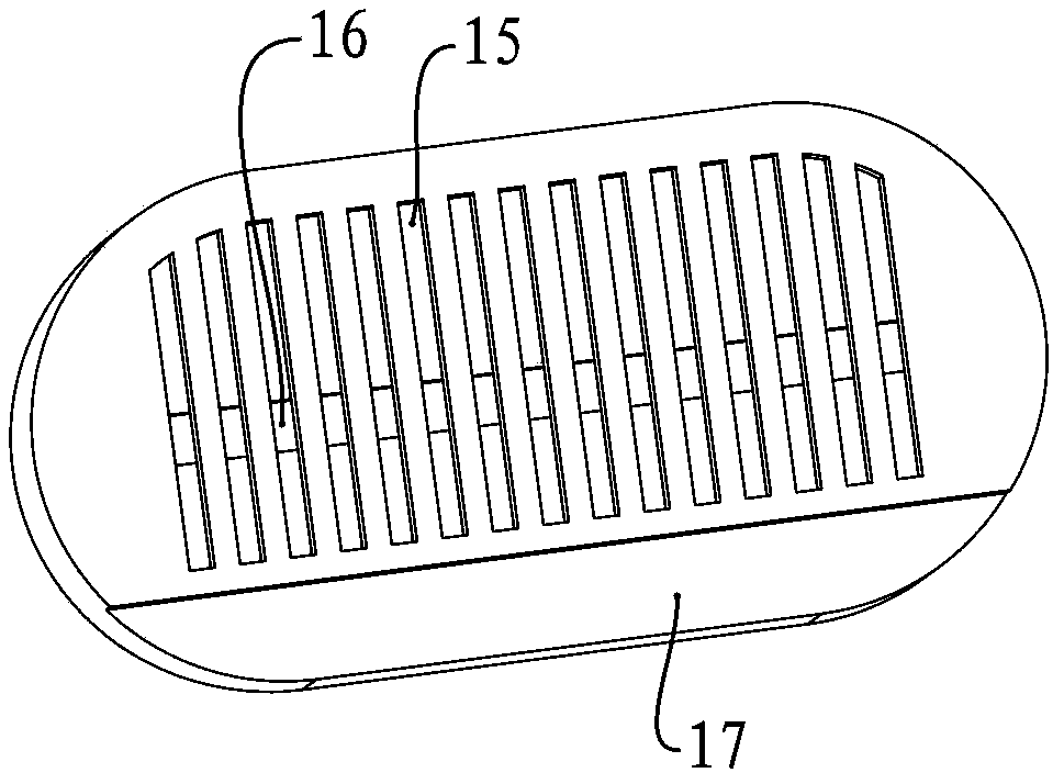
[0024] like figure 1 , figure 2 and Figure 4 As shown, a pressure-compensated dripper includes a dripper base 1 with a water inlet 16, a film 2, and a dripper cover 3 with a water outlet 33. A chamber 11 is provided on the upper side of the dripper base 1. The head cover 3 is installed in the cavity 11, and the cavity 11 is provided with a card slot 12, and the film 2 is installed in the card slot 12 and is located between the dripper base 1 and the dripper cover 3.

[0025] Wherein, the edge around the dripper top cover 3 is close to the inner side wall of the cavity 11, and the liquid enters...


PUM


Abstract

The invention relates to the technical field of drip irrigation, in particular to a pressure compensation type emitter. The pressure compensation type emitter comprises an emitter base with a water inlet hole and an emitter upper cover with a water outlet hole; the upper side of the emitter base is provided with an accommodating cavity; the emitter upper cover is arranged in the accommodating cavity; a clamping groove is formed in the accommodating cavity; a rubber sheet is arranged in the clamping groove; the rubber sheet is positioned between the emitter base and the emitter upper cover; liquid enters the inside of the pressure compensation type emitter through the water inlet hole; the rubber sheet is positioned between the emitter base and the emitter upper cover and the rubber sheet separates the emitter base from the emitter upper cover, and thus, when the liquid enters the inside of the pressure compensation type emitter, the liquid pressure acts on the rubber sheet, the rubber sheet squeezes the emitter upper cover with the water outlet hole and the water passing sectional area is changed, so that flow of the liquid passing through the water outlet hole is enabled to be stabilized in a regulated range. Therefore, the pressure compensation type emitter can be applied to products such as an emitter.

Description

technical field [0001] The invention relates to the technical field of drip irrigation, in particular to a pressure-compensated dripper and a drip irrigation belt / pipe with the pressure-compensated dripper. Background technique [0002] Drip irrigation technology uses drippers on dry pipes, branch pipes and capillary pipes to drip water slowly to the soil under low pressure; it is an irrigation system that directly supplies filtered water, fertilizers or other chemicals to the soil. It doesn't spray or ditch water, it just lets the water trickle out slowly and into the soil by gravity and capillary action. Drips of water near the roots of the crops keep the soil in the main root zone of the crops constantly optimally hydrated. This is an advanced irrigation method. [0003] As the key equipment of drip irrigation technology, the dripper mainly drips water and nutrients into the soil evenly, so that the crops can absorb the required nutrients and water. Most of the existin...

Claims


Application Information

Patent Timeline
IPC IPC(8): B05B1/30
CPCA01G25/023
Inventor 张宇航
Owner SHENZHEN BATIAN ECOTYPIC ENG
Why Eureka
Try Eureka