
A pressing mechanism for jointing of steel pipes

A technology of pressing mechanism and steel pipe, which is applied in auxiliary devices, auxiliary welding equipment, welding/cutting auxiliary equipment, etc. Production efficiency, uniform force, and the effect of improving the pressing effect

Active Publication Date: 2016-06-22
江苏振光电力设备制造有限公司
View PDF6 Cites 0 Cited by
  • Summary
  • Abstract
  • Description
  • Claims
  • Application Information

AI Technical Summary

Problems solved by technology

When the seaming machines at the present stage are used to seam steel pipes, most of them use pressing rollers to press from three directions: top, left, and right. During use, it is found that pressing from only three directions will cause steel pipes to Uneven stress, the pressing process may cause steel pipe deformation, the pressing effect is not good, reducing the production efficiency of the enterprise

Method used


Image

  • A pressing mechanism for jointing of steel pipes
  • A pressing mechanism for jointing of steel pipes
  • A pressing mechanism for jointing of steel pipes

Examples


Embodiment

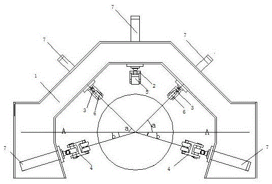
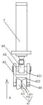
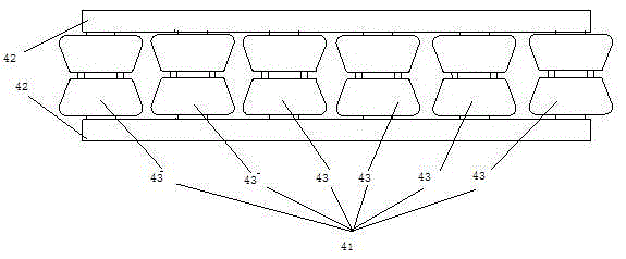
[0020] As shown in the figure, a pressing mechanism for steel pipe joints includes a pressure roller fixing seat 1, wherein the pressure roller fixing seat 1 is an octagonal structural frame with an open cross-sectional shape, and the pressure roller is fixed The seat 1 is provided with a plurality of pressure rollers, including the first pressure roller 2, the second pressure roller 3 and the third pressure roller 4. The first pressure roller 2 is located at the top middle position of the pressure roller fixing seat 1, and the first pressure roller The first roller row arranged at the bottom of the roller 2 is composed of six first circular rollers 5 arranged side by side, and a hydraulic oil cylinder 7 is provided on the top; the number of the second pressure rollers 3 is two, and they are respectively located at the pressure roller fixing seat 1 The position on both sides of the top of the top, with the first pressure roller 2 as the axis of symmetry, two second pressure rol...


PUM


Abstract

The invention discloses a pressing mechanism for jointing of steel pipes. A first pressing roller, a second pressing roller and a third pressing roller are arranged on the pressing roller fixing seat, and the first pressing roller is located on the top of the pressing roller fixing seat The middle position; the two second pressure rollers are located on both sides of the top of the pressure roller fixing seat, and the angle a between the second pressure roller and the horizontal direction is 45 degrees; the width L1 of the first circular roller is the same as that of the second circular roller. The ratio of roller width L2 is 7:6; the two third pressure rollers are located at the bottom of both sides of the pressure roller fixing seat, and the angle b between the third pressure roller and the horizontal direction is 17 degrees, and the third pressure roller includes a roller The wheel row and the receiving bracket. There are multiple pressing rollers in the groove at the bottom of the receiving bracket. The pressing rollers are set by two round table rollers, which are concave in the middle and convex at both ends; the other end of the third pressing roller is connected to a hydraulic cylinder. ;From multiple angles, using a variety of pressing rollers for pressing can effectively avoid the deformation of the steel pipe during pressing, improve the pressing effect, and greatly improve the production efficiency of the enterprise.

Description

technical field [0001] The invention relates to a pressing mechanism, in particular to a pressing mechanism used for jointing of steel pipes. Background technique [0002] At present, most of the large-diameter steel pipes are made of single steel plates, which need to be fixed by spot welding after forming a cylinder to prepare for the welding process. Before spot welding, since the middle seam is left when the steel pipe is reeled, it is necessary to close the seam of the steel pipe. When the seaming machines at the present stage are used to seam steel pipes, most of them use pressing rollers to press from three directions: top, left and right. During use, it is found that pressing from only three directions will cause steel pipes to Due to uneven force, the process of pressing may cause deformation of the steel pipe, and the pressing effect is not good, which reduces the production efficiency of the enterprise. Contents of the invention [0003] The technical problem ...

Claims


Application Information

Patent Timeline
Patent Type & Authority Patents(China)
IPC IPC(8): B21C37/08B23K37/053
Inventor 贾红宝黄国焕李代君蒋胜利
Owner 江苏振光电力设备制造有限公司
Learn More