
Display module and display device

A technology for display modules and display parts, which is applied to identification devices, instruments, electrical components, etc., can solve problems such as unfavorable thinning of modules and increase in thickness of display modules, achieve good support, improve imprinting problems, and avoid problems. The effect of compression deformation

Pending Publication Date: 2021-12-07
WUHAN CHINA STAR OPTOELECTRONICS SEMICON DISPLAY TECH CO LTD
View PDF6 Cites 10 Cited by
  • Summary
  • Abstract
  • Description
  • Claims
  • Application Information

AI Technical Summary

Problems solved by technology

[0004] The embodiment of the present invention provides a display module, which is used to solve the problem of display modules in the prior art by adding a reinforcing steel sheet on the outside of the copper to improve the pressure marks on the display panel during the bending process, but it will cause the display module The overall thickness increases, which is not conducive to the technical problem of thinning the module

Method used


Image

  • Display module and display device
  • Display module and display device
  • Display module and display device

Examples


Embodiment Construction

[0025] The following will clearly and completely describe the technical solutions in the embodiments of the present invention with reference to the drawings in the embodiments of the present invention. In the drawings, for clarity and ease of understanding and description, the size and thickness of the components shown in the drawings are not in scale.

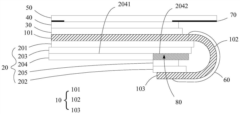
[0026] Such as figure 1 As shown, it is a schematic diagram of the basic structure of the display module provided by the embodiment of the present invention, the display module includes a display panel 10 and a support assembly 20; the display panel 10 includes a display part 101, a bending part 102 and a binding part 103, the binding part 103 is bent to the side of the display part 101 away from the light-emitting side through the bending part 102; one side of the support assembly 20 is attached to the display part 101, and the other side Attached to the binding part 103, the support assembly 20 includes a buffer layer 203 l...


PUM


Abstract

The invention provides a display module and a display device. The display module comprises a display panel and a supporting assembly. The display panel comprises a display part, a bending part and a binding part; one side of the supporting assembly is attached to the display part, the other side of the supporting assembly is attached to the binding part, and the supporting assembly comprises a buffer layer, a composite film layer and a reinforcing layer; the composite film layer comprises a heat dissipation layer and a reinforcing layer arranged on the same layer as the heat dissipation layer, the hardness of the reinforcing layer is larger than that of the heat dissipation layer, and the orthographic projection of the reinforcing layer on the display panel coincides with the orthographic projection of the reinforcing layer on the display panel. According to the display panel, the reinforcing layer and the heat dissipation layer are arranged on the same layer, the hardness of the reinforcing layer is larger than that of the heat dissipation layer, the orthographic projection of the reinforcing layer on the display panel coincides with the orthographic projection of the reinforcing layer on the display panel, the reinforcing layer can provide better supporting force in the bending process, pressing deformation between the reinforcing layer and the heat dissipation layer is avoided, on the premise that the thickness is not increased, the problem of marks caused in the bending process is solved.

Description

technical field [0001] The invention relates to the field of display technology, in particular to a display module and a display device. Background technique [0002] The current OLED (Organic Light Emitting Diode, Organic Light Emitting Diode) display panel usually adopts Pad Bending (binding area bending) technology to achieve the effect of narrow frame, that is, firstly, yellow PI (polyimide) is coated on the glass substrate as Flexible substrate, and then TFT (Thin Film Transistor, thin film transistor) devices are fabricated on the flexible substrate, and then the whole flexible film layer is peeled off from the glass substrate after the module manufacturing process is completed, and then PadBending is performed to bind the The metal traces in the area are bent to the back of the display panel. Usually, the outermost side of the back of the display panel is the SCF (Super Clean Foam) component, which is a laminated structure of foam and copper. Because the material of ...

Claims


Application Information

Patent Timeline
Patent Type & Authority Applications(China)
IPC IPC(8): H01L23/00G09F9/33
CPCH01L23/564G09F9/33Y02E10/549
Inventor 陈荣坤
Owner WUHAN CHINA STAR OPTOELECTRONICS SEMICON DISPLAY TECH CO LTD
Learn More