
Pressing head of connecting rod bushing pressing clamp

A technology of pressing head and pressing lining, which is applied in the direction of connecting rod, manufacturing tools, metal processing, etc. It can solve the problems that affect the fitting degree of bushing and connecting rod, and cannot meet the requirements of drawing fitting degree, so as to prevent pressing deformation , The effect of high assembly efficiency

Active Publication Date: 2016-04-06
HANGZHOU JIULONG MACHINERY MFG
View PDF6 Cites 0 Cited by
  • Summary
  • Abstract
  • Description
  • Claims
  • Application Information

AI Technical Summary

Problems solved by technology

[0002] The small head of the connecting rod needs to be press-fitted with a bushing, which is wear-resistant and prolongs the service life of the connecting rod. In the past, the two sides of the small head of the connecting rod are flat (the bushing is also flat), and the bushing is pressed in and then processed into a slope. The advantage is that it is convenient for pressing and manufacturing, but the disadvantage is that it needs to be reprocessed, which will affect the fit of the bushing and the connecting rod.
In order to overcome this deficiency, the plane of the small end of the connecting rod is designed as an inclined plane and the bushing matched with the small end is also inclined. Since the bush is affected by the radial force at the moment it enters the small end, the existing compression The installation method can not meet the requirements of drawing fit degree

Method used


Image

  • Pressing head of connecting rod bushing pressing clamp
  • Pressing head of connecting rod bushing pressing clamp
  • Pressing head of connecting rod bushing pressing clamp

Examples


Embodiment 1

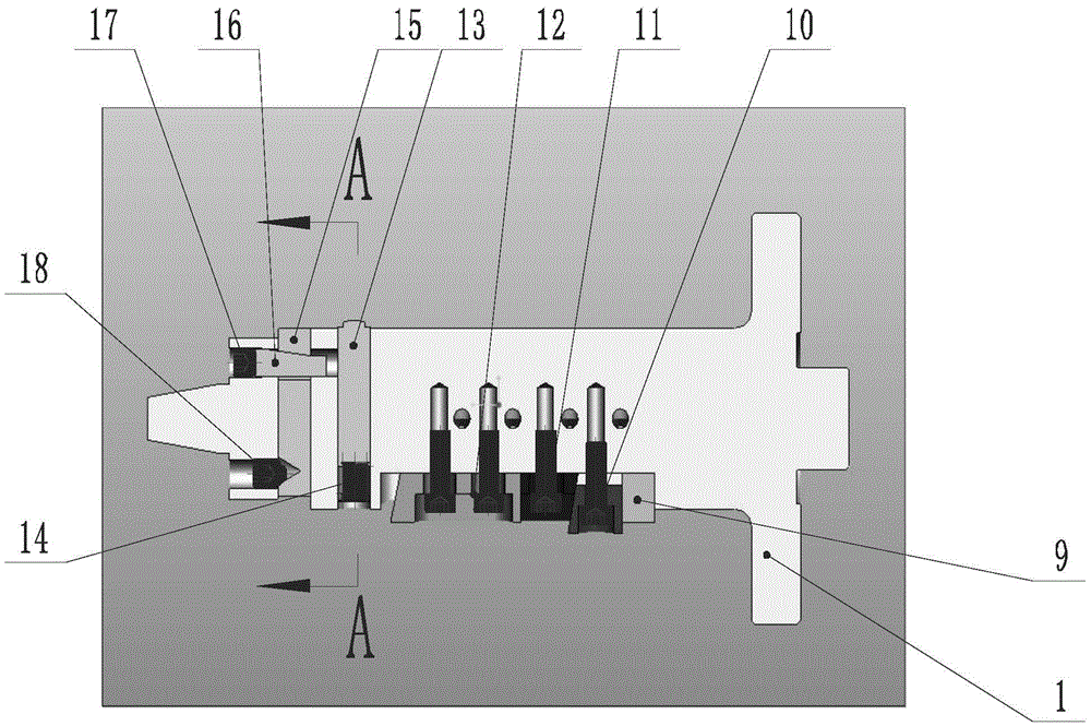
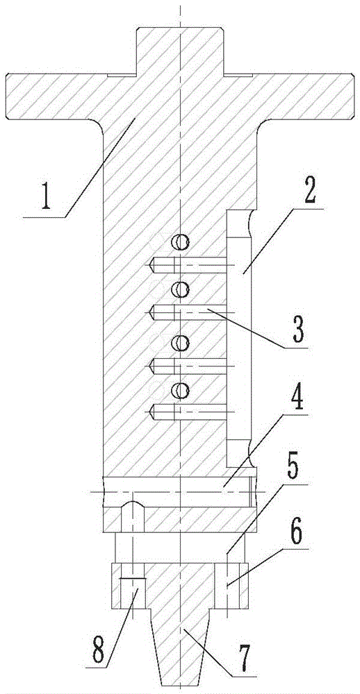
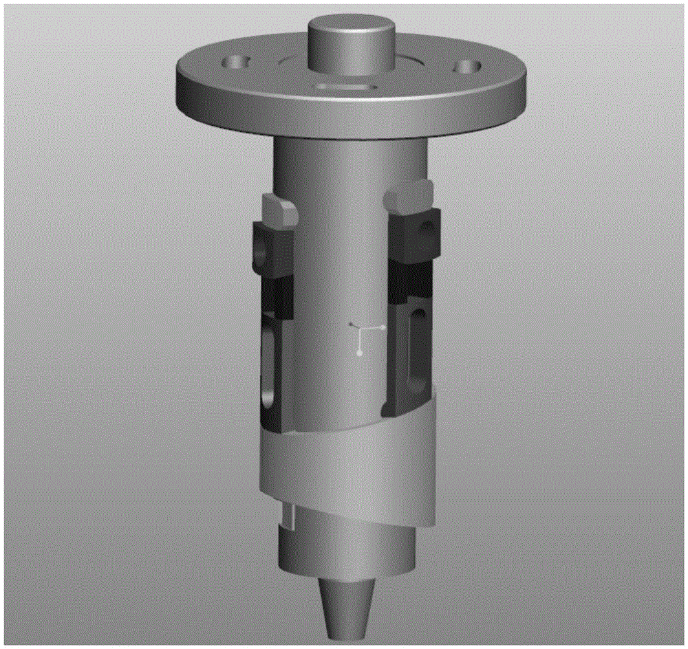
[0013] Embodiment 1: with reference to attached Figure 1-6 . An indenter for a connecting rod pressing bushing jig is characterized in that: the upper end of the indenter 1 is a machine tool connection surface 1, the lower end of the indenter 1 is a tapered column 7, and the head and body of the indenter 1 are provided with a plurality of grooves 2, each There are multiple countersunk holes 3 horizontally tapped on the bottom of the groove 2 from top to bottom. The lower part of the groove 2 is horizontally opened with a head hole 4 and a through hole 5 from top to bottom. The through thread hole 6 and the two-way through thread button hole 8; the pressing block 12, the lower wedge-shaped block 11, the upper wedge-shaped block 10, and the cushion block 9 are superimposed in sequence from bottom to top in the groove 2, and the pressing block 12, the lower wedge-shaped block The shape block 11 and the upper wedge shape block 10 are screwed with the respective countersunk screw...

Embodiment 2

[0014] Embodiment 2: On the basis of Embodiment 1, a connecting rod pressing bushing jig composed of an indenter for the connecting rod pressing bushing jig is shown in the attached Figure 3-6 and text description.


PUM


Abstract

The invention relates to a pressing head of a connecting rod bushing pressing clamp, which can quickly, conveniently and snugly press a bevel bushing into a small-end bevel hole of a connecting rod. A machine tool connecting surface is arranged at the upper end of the pressing head; a tapered column is arranged at the lower end of the pressing head; a plurality of grooves are formed in the body of the pressing head; a plurality of countersunk screw holes are transversely tapped in the bottom surface of each groove from top to bottom; a sealing head hole and a through hole are transversely formed below the grooves from top to bottom; a one-way through screw hole and a two-way through screw hole are formed in a step surface of the tapered column; pressing blocks, lower wedge blocks, upper wedge blocks and cushion blocks are stacked in the grooves from bottom to top in sequence; the pressing blocks, the lower wedge blocks and the upper wedge blocks are in threaded connection with the respective countersunk screw holes through inner hexagon screws; a positioning rod is located in the sealing head hole through a pressure spring; a V-shaped countersunk hole and a tapered hole are formed in the body of an ejector rod; the ejector rod is located in the through hole; an inner hexagon screw fits in the V-shaped countersunk hole in the ejector rod through the one-way through screw hole; and a fine adjustment rod gets into the tapered hole in the ejector rod through the two-way through screw hole and is positioned through an inner hexagon screw.

Description

technical field [0001] The invention relates to an indenter for a connecting rod bushing fixture and a pressing method capable of quickly, conveniently and fittingly pressing the inclined bushing into the inclined hole of the small end of the connecting rod, which belongs to the pressing method for the bushing of the small end of the connecting rod. field of tooling manufacturing. Background technique [0002] The small head of the connecting rod needs to be press-fitted with a bush, which is wear-resistant and prolongs the service life of the connecting rod. In the past, the two sides of the small head of the connecting rod are flat (the bush is also flat), and the bush is pressed in and then processed into a slope. The advantage is that it is convenient for pressing and manufacturing, but the disadvantage is that it needs to be reprocessed, which will affect the degree of fit between the bush and the connecting rod. In order to overcome this deficiency, the plane of the s...

Claims


Application Information

Patent Timeline
IPC IPC(8): B23P19/02
CPCB23P19/02B23P2700/04
Inventor 孟波巩赵飞刘岚泽欧阳广
Owner HANGZHOU JIULONG MACHINERY MFG
Learn More