
Small-angle tilting mechanism of engine for small tilt rotor aircraft

A technology of tilting rotorcraft and tilting mechanism, which is applied in the small-angle tilting mechanism of the engine and the field of small tilting rotorcraft. Use value, easy-to-achieve effect

Inactive Publication Date: 2014-12-03
SHANGHAI DONGGU AVIATION TECH CO LTD
View PDF4 Cites 15 Cited by
  • Summary
  • Abstract
  • Description
  • Claims
  • Application Information

AI Technical Summary

Problems solved by technology

[0003] For the tilting rotorcraft, there is a set of tilting mechanism itself so that the engine and the propeller can rotate within a range of about 90 degrees, but if this mechanism is used to execute the control command of the controller, the tilting rotorcraft will change The flight state and the process of tilting the engine at a large angle will lead to the coupling of the two control commands, which may cause control failure, which is not conducive to the stability and safety of aircraft control

Method used


Image

  • Small-angle tilting mechanism of engine for small tilt rotor aircraft
  • Small-angle tilting mechanism of engine for small tilt rotor aircraft
  • Small-angle tilting mechanism of engine for small tilt rotor aircraft

Examples


Embodiment Construction

[0032] In this embodiment, the engine small-angle tilting mechanism of a small tiltrotor is taken as an example to illustrate the design and working principle of each part of the tilting mechanism.

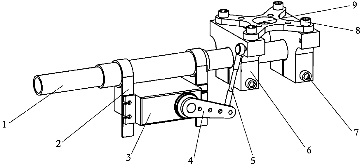
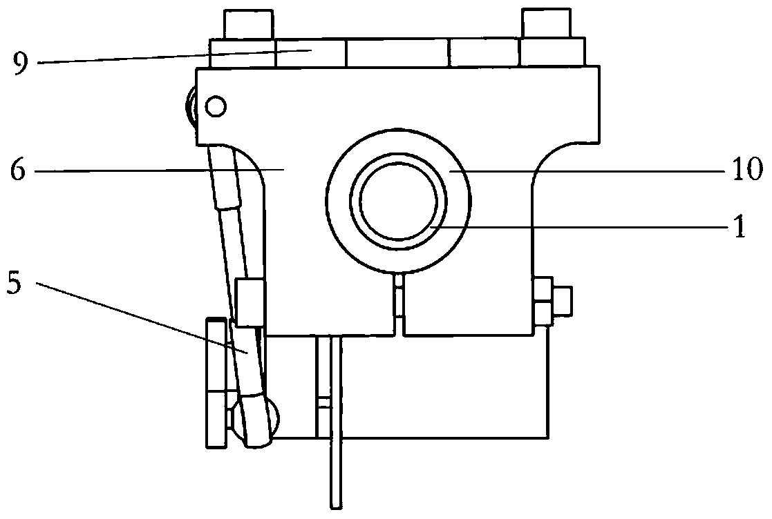
[0033] figure 1 is a three-dimensional schematic diagram of the mechanism, figure 2 is its right view.

[0034] The invention is an engine small-angle tilting mechanism for a small tilting rotorcraft, which includes: a tilting main shaft 1, a steering gear fixing frame 2, a servo steering gear 3, a steering gear disc 4, a ball head rod assembly 5, Engine frame 6 (left and right two), frame fastening bolt 7, frame fastening bolt 8, engine mount 9, frame rotating bearing 10. Such as figure 1As shown, the position connection relationship between them is: one end of the tilting main shaft 1 is connected to the fuselage (not shown in the figure) and the other end is connected to the mechanism; wherein, the servo steering gear 3 is connected to the tilting body through two steering ...


PUM


Abstract

The invention discloses a small-angle tilting mechanism of an engine for a small tilt rotor aircraft. The small-angle tilting mechanism of the engine comprises a tilting main shaft, a steering engine fixing frame, a servo steering engine, a steering engine plate, a ball head tie rod assembly, left and right engine bases, engine base fastening bolts, an engine fixing frame, a rack fastening bolt and an engine base rotating bearing, wherein the tilting main shaft is connected with a machine body; the servo steering machine is connected to the tilting main shaft through the steering engine fixing frame, and is connected with the steering engine fixing frame through bolts; a take-up device is arranged on the steering engine fixing frame and used for loading, unloading and moving the steering engine fixing frame on the tilting main shaft; the steering machine plate is inserted into an output shaft of the servo steering machine; one end of the ball head tie rod assembly is connected with the steering machine plate; the other end of the ball head tie rod assembly is connected with the left engine base; the left engine base and the right engine base are connected to the tilting main shaft through engine base rotating bearings; the axial positioning and circumferential positioning of the left engine base and the right engine base are achieved through the engine base rotating bearings; and the engine fixing frame is fixed on the left engine base and the right engine base through four rack fixing bolts.

Description

technical field [0001] The invention belongs to the technical field of aero-engine tilting, and in particular relates to an engine small-angle tilting mechanism for a small tilting rotorcraft. It is a mechanism that can drive the engine to tilt within a small angle, and can be applied Small tilt rotor aircraft. Background technique [0002] For some small tiltrotor aircraft or general two-axis aircraft, the stability of the pitch and yaw attitude in the hovering state must be achieved by tilting the engine within a certain range to make the propeller tension line deviate from the center of gravity. The stability of attitude requires a set of sensitive and reliable tilting mechanism to execute the control commands issued by the controller. [0003] For the tilting rotorcraft, there is a set of tilting mechanism itself so that the engine and the propeller can rotate within a range of about 90 degrees, but if this mechanism is used to execute the control command of the control...

Claims


Application Information

Patent Timeline
IPC IPC(8): B64C27/28B64C27/52
Inventor 周尧明于沿蒙志君陈旭智何维
Owner SHANGHAI DONGGU AVIATION TECH CO LTD
Learn More