Rail fastener system without elastic strips

A technology of track fasteners and elastic strips, which is applied in the direction of tracks, roads, fixed rails, etc., can solve problems such as reducing the pressure of elastic strips, corrosion of iron backing plates, and easy breakage, so as to improve safety and reliability, and alleviate Corrosion problems, the effect of preventing left and right shaking

Active Publication Date: 2014-12-03
HEBEI YICHEN INDAL GROUP +1
View PDF6 Cites 11 Cited by
  • Summary
  • Abstract
  • Description
  • Claims
  • Application Information

AI Technical Summary

Problems solved by technology

[0003] In addition to urban subways and light rails, many cities have begun to develop tram lines. The rails of trams are different from those used in subways and light rails. They are grooved rails, and the width and slope of the rail bottom are different from ordinary rails; and Fasteners need to be pre-buried in the ground, which are prone to corrosion and cannot be maintained frequently. The design and protection requirements for fasteners are higher; ordinary fasteners cannot be applied to trams, and a new fastener needs to be developed to meet the laying requirements of tram tracks. need
[0004] The existing technology mainly uses ω elastic clips or e-shaped elastic clips, and nodular cast iron backing plates. Since the fasteners of the tram are buried underground, the fasteners are often in a wet state, and corrosion problems often occur, especially after the elastic clips are corroded. The appearance of oxide layer and corroded concave surface will reduce the buckle pressure of the elastic strip, and it is easy to break. The iron backing plate is rusted and easy to break, which seriously threatens driving safety.

Method used


Image

  • Rail fastener system without elastic strips
  • Rail fastener system without elastic strips
  • Rail fastener system without elastic strips

Examples


Embodiment Construction

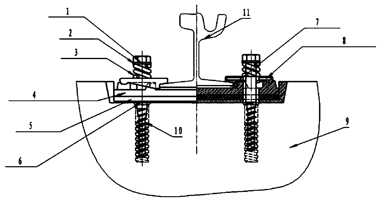
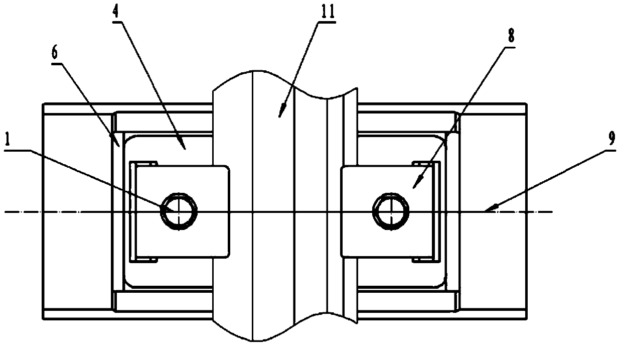
[0021] The present invention will be further described below in conjunction with accompanying drawing:

[0022] like figure 1 , figure 2 , image 3 , Figure 4 , Figure 5 , Figure 6 As shown, the rail fastening system without elastic strips includes a gauge backing plate 6 with a concave vertical cross-sectional shape arranged in the groove of the concrete sleeper 9, and an elastic backing plate 5 under the board is arranged above the gauge backing plate 6. A backing plate 4 is arranged above the lower elastic backing plate 5, and two positioning blocks 12 are symmetrically arranged on the upper surface of the backing plate 4, and the under-rail backing plate 7 is arranged in the groove between the two positioning blocks 12, and the rail of the rail 11 The bottom is placed on the backing plate 7 under the rail. The size of the backing plate 7 matches the size of the bottom surface of the rail bottom of the rail 11. The lower surface of one end of the nylon gauge buckle...


PUM


Abstract

The invention provides a rail fastener system without elastic strips. A board lower resilient sleeper bearing is arranged above a gauge plate; a base plate is arranged above the board lower resilient sleeper bearing; a rail lower base plate is arranged above the base plate; a steel rail is placed on the upper surface of the rail lower base plate; a fixing piece is a nylon gauge clip; the nylon gauge clip is made of glass fiber reinforced nylon 66; the lower surface of one end of the nylon gauge clip is in contact with the upper surface of one end of a steel rail bottom; an inclined surface of one end of the nylon gauge clip is matched with an inclined surface of the upper surface of one end of the steel rail bottom; the lower surface of the other end of the nylon gauge clip is in contact with the upper surface of the base plate; and a screw spike sequentially penetrates in the nylon gauge clip, the base plate, the board lower resilient sleeper bearing and the gauge plate and then is matched with a concrete sleeper in a locked manner. The rail fastener system is simple in structure; the fastening strength of the rail fastener system without the elastic strips is equivalent to that of a rail fastener system with elastic strips, but the cost is reduced by a third; corrosion can be effectively relieved; the service life of the rail fastener system is prolonged; effects of noise reduction and shock absorption can be achieved; and the safety and the reliability of a vehicle in a running process are improved.

Description

technical field [0001] The invention belongs to the technical field of fasteners for railway tracks, and relates to a fastener system, in particular to a rail-free fastener system for urban subways, light rails and trams. Background technique [0002] In recent years, domestic urban rail transit systems such as urban subways, light rails, and trams have developed rapidly, effectively alleviating the tension in urban traffic. In urban rail construction, rail fastener systems are indispensable. Fasteners are used to connect rails and concrete sleepers or integral ballast beds, and fix rails on concrete sleepers or integral ballast beds. The original rail fastener system includes iron backing plates, spring bars, rubber backing plates, nylon parts, bolts, etc. Spring bar installation In the spring bar hole of the iron backing plate, through elastic deformation, a downward buckle pressure is generated on the rail to fix the rail to prevent the rail from shaking when the train pa...

Claims


Application Information

Patent Timeline
Patent Type & Authority Applications(China)
IPC IPC(8): E01B9/04
Inventor 和增礼王晓谦李军广王丽娜
Owner HEBEI YICHEN INDAL GROUP
Why Eureka
Try Eureka