Vehicle power transmission device

A technology for power transmission devices and vehicles, which is applied in the direction of transmission devices, transmission device parts, roller bearings, etc., can solve the problems of increasing the number of parts, large-scale axial dimensions of power transmission devices for vehicles, etc., and achieve improved coaxiality and Rigid effect

Active Publication Date: 2016-08-17
HONDA MOTOR CO LTD
View PDF5 Cites 0 Cited by
  • Summary
  • Abstract
  • Description
  • Claims
  • Application Information

AI Technical Summary

Problems solved by technology

[0004] However, around the output shaft of a vehicle power transmission device equipped with a plurality of crank-type transmission units, in addition to bearings that support the output shaft to the transmission case, it is necessary to connect the axial two sides of the swing connectors of the plurality of transmission units. A pair of bearings are side-supported by the output shaft. Since so many bearings are arranged on the outer periphery of the output shaft, there are problems such as an increase in the number of parts and an increase in the axial dimension of the vehicle power transmission device.

Method used


Image

  • Vehicle power transmission device
  • Vehicle power transmission device
  • Vehicle power transmission device

Examples


Embodiment Construction

[0028] Below, based on Figure 1 to Figure 12 Embodiments of the present invention will be described.

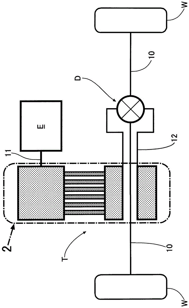
[0029] Such as figure 1 As shown, the power transmission device for a vehicle that transmits the driving force of the engine E to the drive wheels W, W through the left and right axles 10 , 10 includes a crank type continuously variable transmission T and a differential D.

[0030] Next, based on Figure 2 ~ Figure 6 The structure of the continuously variable transmission T will be described.

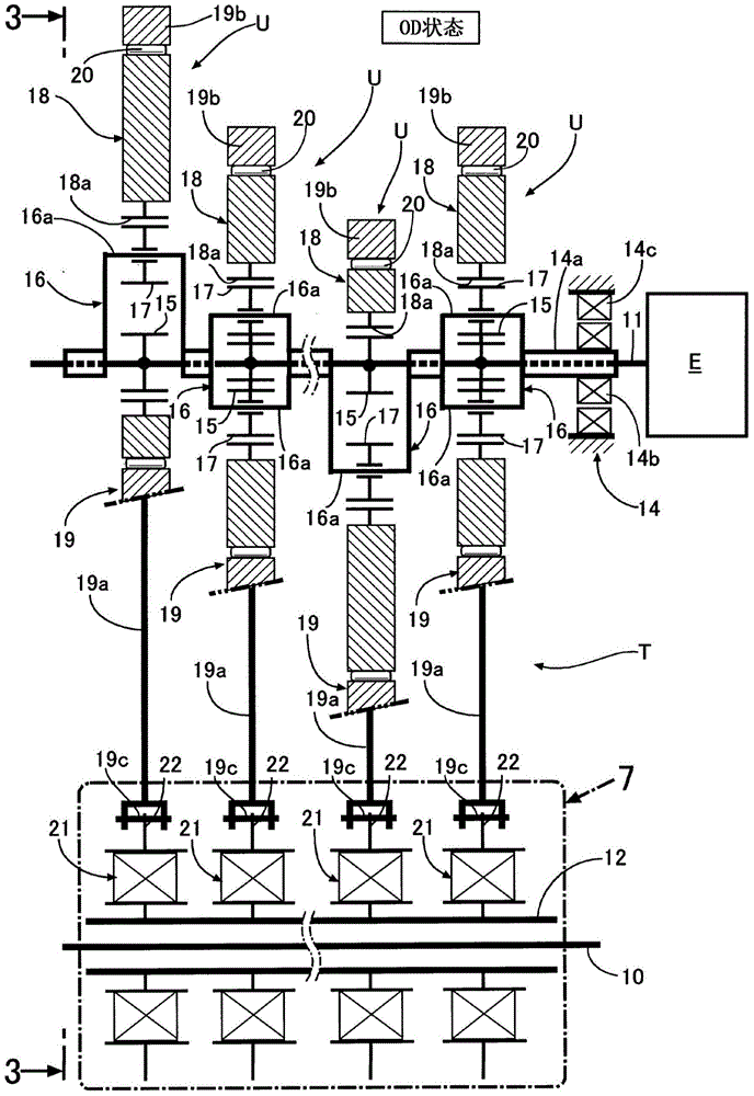
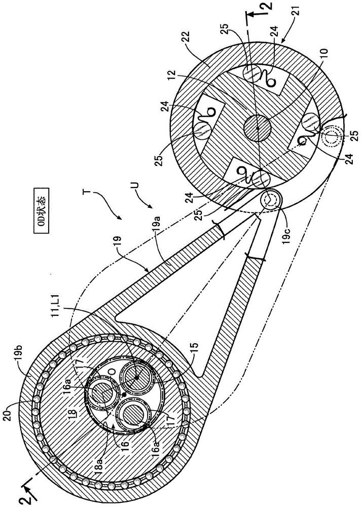
[0031] Such as figure 2 with image 3 As shown, the continuously variable transmission T of this embodiment is obtained by stacking a plurality of (six in the embodiment) transmission units U... having the same structure in the axial direction, and these transmission units U... have A common input shaft 11 and a common output shaft 12 , the rotation of the input shaft 11 being decelerated or accelerated is transmitted to the output shaft 12 .

[0032] Hereinafter, the configura...


PUM


Abstract

A power transmission device for a vehicle. The number of parts of the bearings around the output shaft of the vehicle power transmission device having the crank type transmission unit can be reduced. It includes output shaft support bearings (27, 28) for supporting the output shaft (12) on the transmission housing (26), and swing bearings (27, 28) for supporting both axial sides of each swing connector (22) on the output shaft (12). Connector support bearings (34, 34'), the inner rings (41, 44) of the output shaft support bearings (27, 28), and the inner rings (41, 44) of the swing connector support bearings (34') The adjacent inner rings (36') are integrally formed. Therefore, compared with the case where the inner rings of the output shaft support bearing and the inner rings of the swing connector support bearings are composed of different parts, not only the number of parts can be reduced, but also the power of the vehicle can be reduced. The miniaturization of the axial dimension of the transmission device can also improve the coaxiality and rigidity of the output shaft support bearing and the swing connector support bearing.

Description

technical field [0001] The present invention relates to a power transmission device for a vehicle including a plurality of crank-type transmission units that transmit the rotation of an input shaft connected to a drive source to an output shaft after speed-changing. Background technique [0002] In order to rotatably support the rotor of the motor on the stator, the following patent document 1 has known a structure in which one ring of a thrust ball bearing is fixed to the rotor and the other ring of a radial ball bearing supports the shaft of the rotor to the stator. Outer ring abutment. [0003] Patent Document 1: Japanese Utility Model Publication No. 3-3155 [0004] However, around the output shaft of a vehicle power transmission device equipped with a plurality of crank-type transmission units, in addition to bearings that support the output shaft to the transmission case, it is necessary to connect the axial two sides of the swing connectors of the plurality of transm...

Claims


Application Information

Patent Timeline
Patent Type & Authority Patents(China)
IPC IPC(8): F16H57/023F16H57/021F16C19/36
CPCF16H29/04
Inventor 牧美里垣内浩树
Owner HONDA MOTOR CO LTD
Why Eureka
Try Eureka