Eureka AIR delivers breakthrough ideas for toughest innovation challenges, trusted by R&D personnel around the world.

Stop valve

A globe valve and valve body technology, applied in the field of globe valves, can solve the problems of high use cost of globe valves, increase in manufacturing cost, increase in operating procedures, etc., and achieve the effects of avoiding the problem of refrigerant leakage, enhancing refrigeration capacity, and reducing use costs.

Inactive Publication Date: 2014-12-03
ZHEJIANG SANHUA INTELLIGENT CONTROLS CO LTD
View PDF5 Cites 8 Cited by
  • Summary
  • Abstract
  • Description
  • Claims
  • Application Information

AI Technical Summary

Problems solved by technology

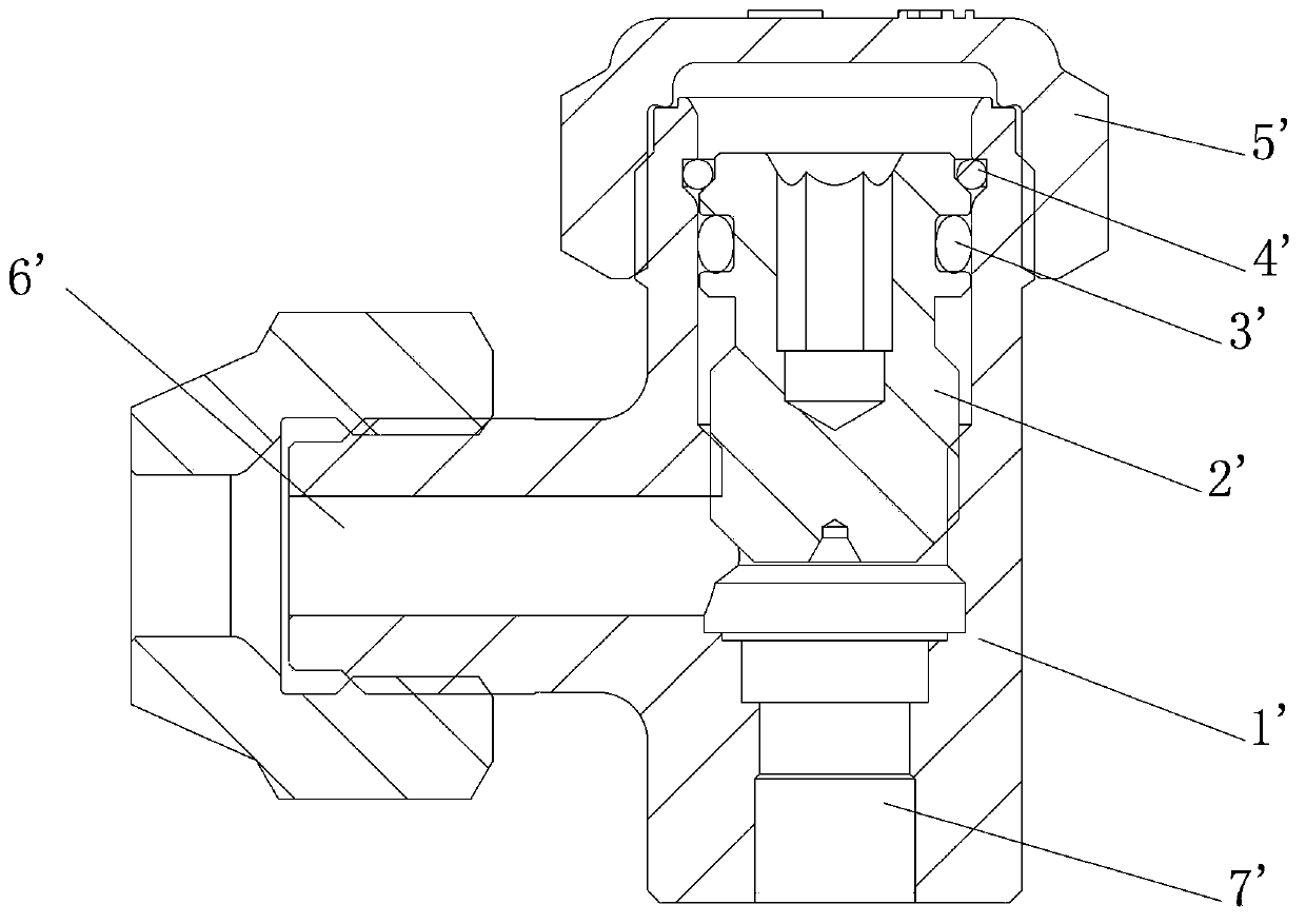
[0007] The valve stem 2' and the valve body 1' in the above globe valve are sealed by the sealing part 3'. During the operation of the valve stem 2', the sealing part 3' and the valve stem 2' move in a spiral shape together, that is, there are axial and radial movement, causing wear and flanging on the surface of the sealing part 3', which can easily lead to leakage at the 3' part of the sealing part, reducing the cooling medium, reducing the cooling capacity and performance of the refrigeration equipment
[0008] In addition, in order to meet the needs of the spiral movement of the sealing part 3' inside the valve body 1', the outer diameter of the valve body 1' is generally relatively large, resulting in a relatively high cost of use for the globe valve, and the external use of the bonnet 5' for secondary sealing , increasing the operation process, and the manufacturing cost increases accordingly

Method used


Image

  • Stop valve
  • Stop valve
  • Stop valve

Examples


Embodiment Construction

[0033] The core of the present invention is to provide a shut-off valve, the valve stem and the valve body of the shut-off valve have high sealing performance.

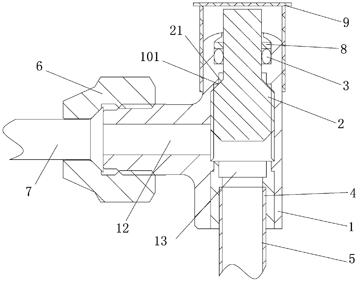
[0034] This article takes the use of the stop valve in the air conditioning system as an example to introduce the technical effect of the stop valve provided by the present invention. Those skilled in the art should understand that the stop valve provided by the present invention includes but is not limited to the application in the air conditioning system ; In order to enable those skilled in the art to better understand the technical solution of the present invention, the present invention will be further described in detail below in conjunction with the accompanying drawings and specific embodiments.

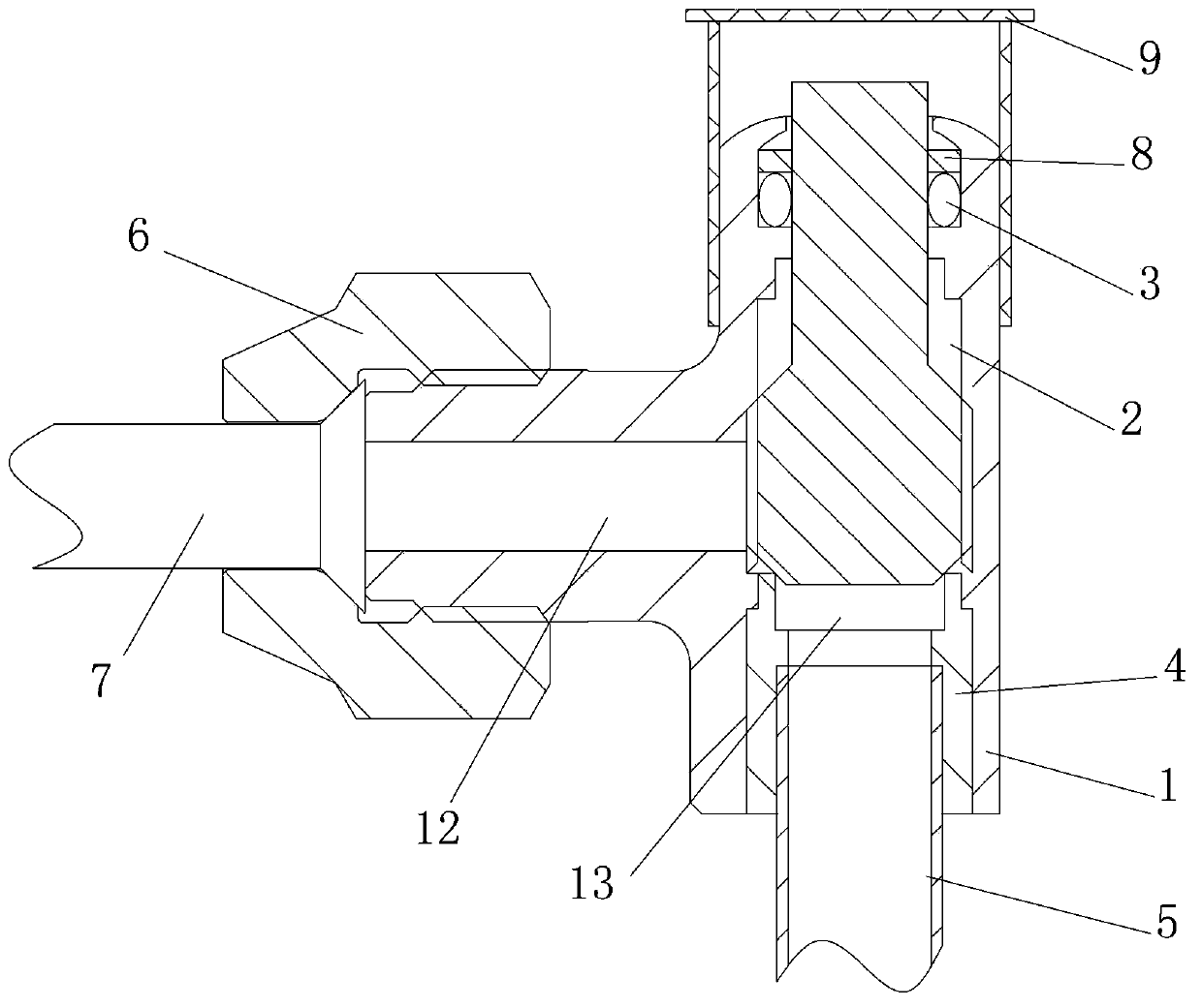
[0035] Please refer to figure 2 , figure 2 It is a schematic structural diagram of a shut-off valve in a specific embodiment provided by the present invention; image 3 for figure 2 Schematic diagram of the str...


PUM


Abstract

The invention discloses a stop valve. The stop valve comprises a valve body provided with a first valve port and a second valve port; the two valve ports are communicated through a medium channel inside the valve body. The stop valve also comprises a valve rod which is arranged in a valve body inner cavity of the valve body and is used for disconnecting or connecting the medium channel and a sealing part used for circumferentially sealing the valve rod and the valve body; the sealing part is fixedly arranged on the valve body. The sealing part between the valve rod and the valve body is fixedly arranged on the valve body, so that when the valve rod moves in the valve body inner cavity in the valve body, the sealing part is always positioned in the stationary state and cannot move together with the valve rod in the moving process of the valve rod, the problem that the sealing part and the valve rod move spirally together to cause abrasion and flanging in the prior art is solved, the leakage of a refrigerating medium in the moving process of the sealing part is avoided, and the refrigerating capacity of refrigerating equipment is improved.

Description

technical field [0001] The invention relates to the technical field of valves, in particular to a shut-off valve. Background technique [0002] Valves are ubiquitous in the production of the national economy, and they are closely related to production, construction and people's lives. Valves are control components installed in fluid delivery systems such as various pipelines and equipment, and have functions such as diversion, cut-off, and throttling. [0003] Please refer to figure 1 , figure 1 It is a structural schematic diagram of a typical shut-off valve in the prior art. [0004] The globe valve in the prior art mainly includes valve body 1', valve stem 2', sealing part 3', stop ring 4', bonnet 5' and other components. Generally, the valve stem 2' is set on the valve body 1' In the inner cavity of the valve, the valve stem 2' is provided with an external thread, and the inner wall of the valve inner cavity is provided with an internal thread that matches the extern...

Claims


Application Information

Patent Timeline
IPC IPC(8): F16K41/02F16K27/04
CPCF16K1/38F16K27/0254F16K41/02
Inventor 不公告发明人
Owner ZHEJIANG SANHUA INTELLIGENT CONTROLS CO LTD
Why Eureka
Eureka Blog
Learn More