Scanning tunneling microscope scanning probe head

A technology for scanning probes and tunnels, applied in the field of scanning probes, can solve the problems of large, complex and unstable design structures, and achieve the effects of low noise, high rigidity and high stability

Inactive Publication Date: 2014-12-03
INST OF PHYSICS - CHINESE ACAD OF SCI
View PDF5 Cites 7 Cited by
  • Summary
  • Abstract
  • Description
  • Claims
  • Application Information

AI Technical Summary

Problems solved by technology

This design structure is relatively large and complex, and it is easy to introduce noise and instability
The other is to integrate the sample holder and the scanning base. This structure has better rigidity and stability, but due to the limitation of integrated processing, the space of the scanning probe is narrow and closed, and it is usually difficult to observe the needle tip and sample, unable to monitor the operation process

Method used


Image

  • Scanning tunneling microscope scanning probe head
  • Scanning tunneling microscope scanning probe head
  • Scanning tunneling microscope scanning probe head

Examples


Embodiment Construction

[0021] In order to make the object, technical solution and advantages of the present invention more clear, the present invention will be further described in detail below in conjunction with specific embodiments. It should be understood that the specific embodiments described here are only used to explain the present invention, not to limit the present invention.

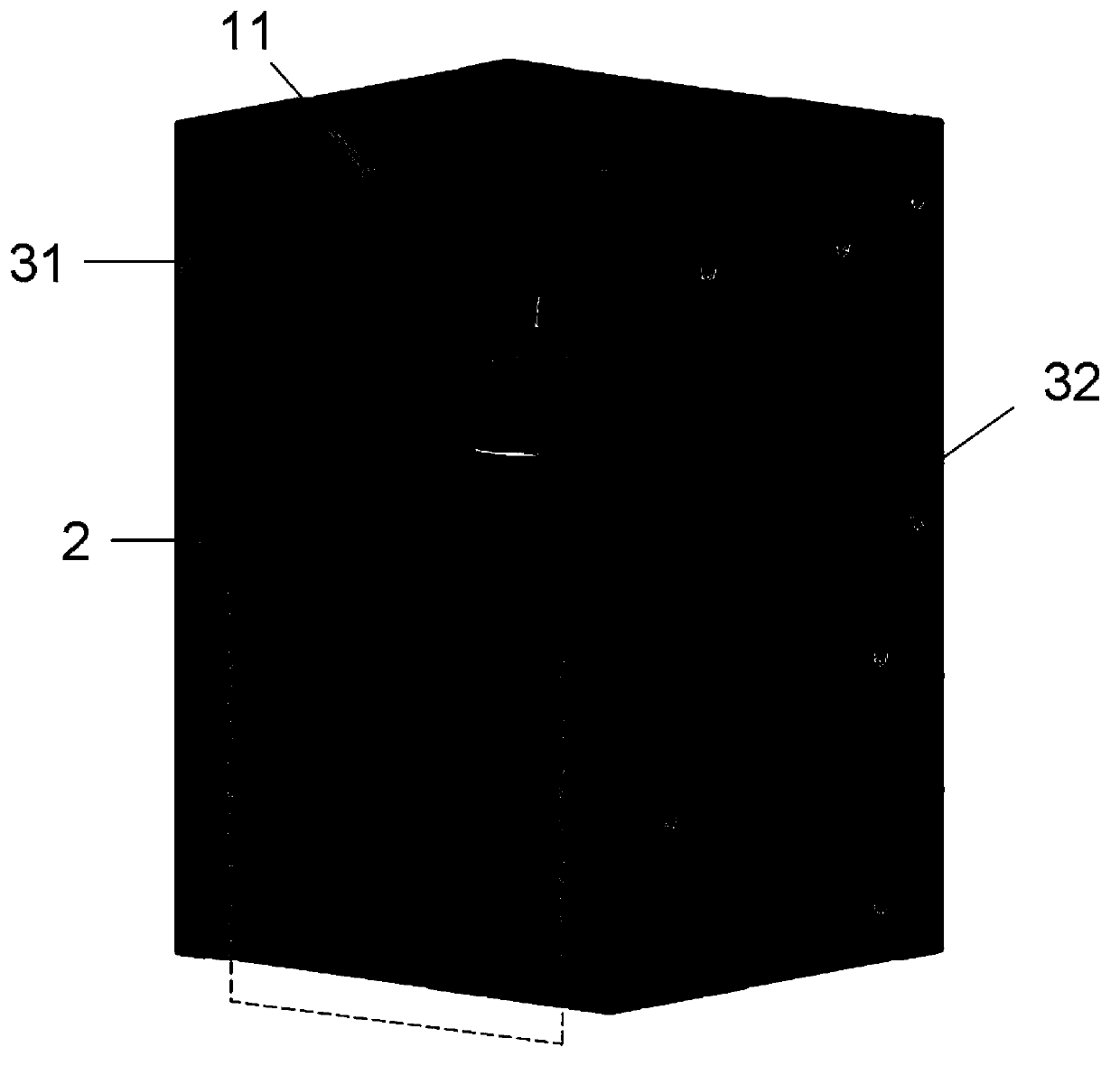
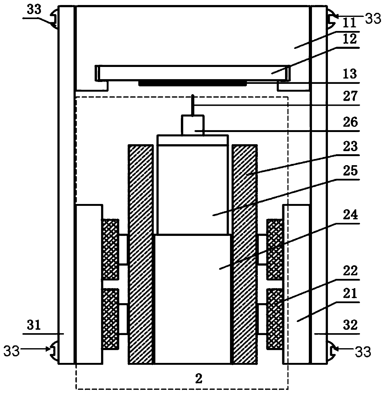
[0022] This embodiment provides a scanning tunneling microscope scanning probe, its three-dimensional structure is as follows: figure 1 As shown, it includes the sample seat 11 and the side plates 31 and 32 on both sides thereof, and the cavity surrounded by the sample seat 11 and the side plates 31 and 32 has the scanning base 2 . figure 2 for figure 1 A cross-sectional view of the scanning probe is shown, as figure 2 As shown, the scanning probe includes:

[0023] The sample holder 11 has a groove, which is used to place a sample holder 12 with a sample 13 in the groove;

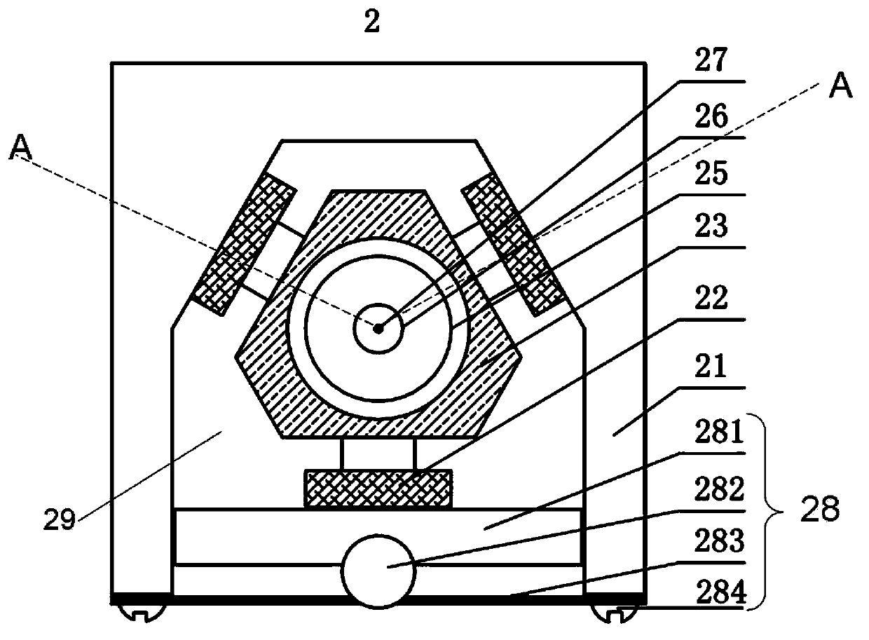
[0024] The scanning base 2 is used ...


PUM


Abstract

The invention provides a scanning tunneling microscope scanning probe head comprising a sample base which is used for bearing a sample; a scanning pedestal which is used for controlling a scanning probe; and a side plate which is used for rigidly connecting the sample base and the scanning pedestal.

Description

technical field [0001] The invention relates to a scanning probe of a scanning tunneling microscope (STM), in particular to an optically compatible low-temperature scanning probe. Background technique [0002] Since its introduction in 1981, scanning tunneling microscopes have been widely used in many fields such as surface physics science, material science, and life science. The scanning tunneling microscope has extremely high spatial resolution, reaching 0.1nm laterally and 0.01nm vertically. Its appearance enables people to "see" and "manipulate" atoms, thus greatly promoting and promoting the development of nanotechnology. The scanning probe is the core part of the scanning tunneling microscope. It is based on the tunneling effect in quantum mechanics, using a metal needle tip as a probe, making it and the sample surface as two electrodes, when the distance between the sample surface and the needle tip is very close (<1nm), the electron clouds of the two are slightl...

Claims


Application Information

Patent Timeline
Patent Type & Authority Applications(China)
IPC IPC(8): G01Q60/16
Inventor 吴克辉何小月
Owner INST OF PHYSICS - CHINESE ACAD OF SCI
Why Eureka
Try Eureka