Folding type scanning optical system based on MEMS micro mirror

An optical system and folding technology, applied in the field of optics, can solve the problem of small scanning field of view and achieve the effect of small spot, large scanning field of view and fast scanning speed

Active Publication Date: 2014-12-03
HARBIN INST OF TECH
View PDF6 Cites 10 Cited by
  • Summary
  • Abstract
  • Description
  • Claims
  • Application Information

AI Technical Summary

Problems solved by technology

[0005] The present invention is to solve the problem of small scanning field of view in the existing MEMS scanning system, and the present invention provides a MEMS folded scanning optical system

Method used


Image

  • Folding type scanning optical system based on MEMS micro mirror
  • Folding type scanning optical system based on MEMS micro mirror
  • Folding type scanning optical system based on MEMS micro mirror

Examples


specific Embodiment approach 1

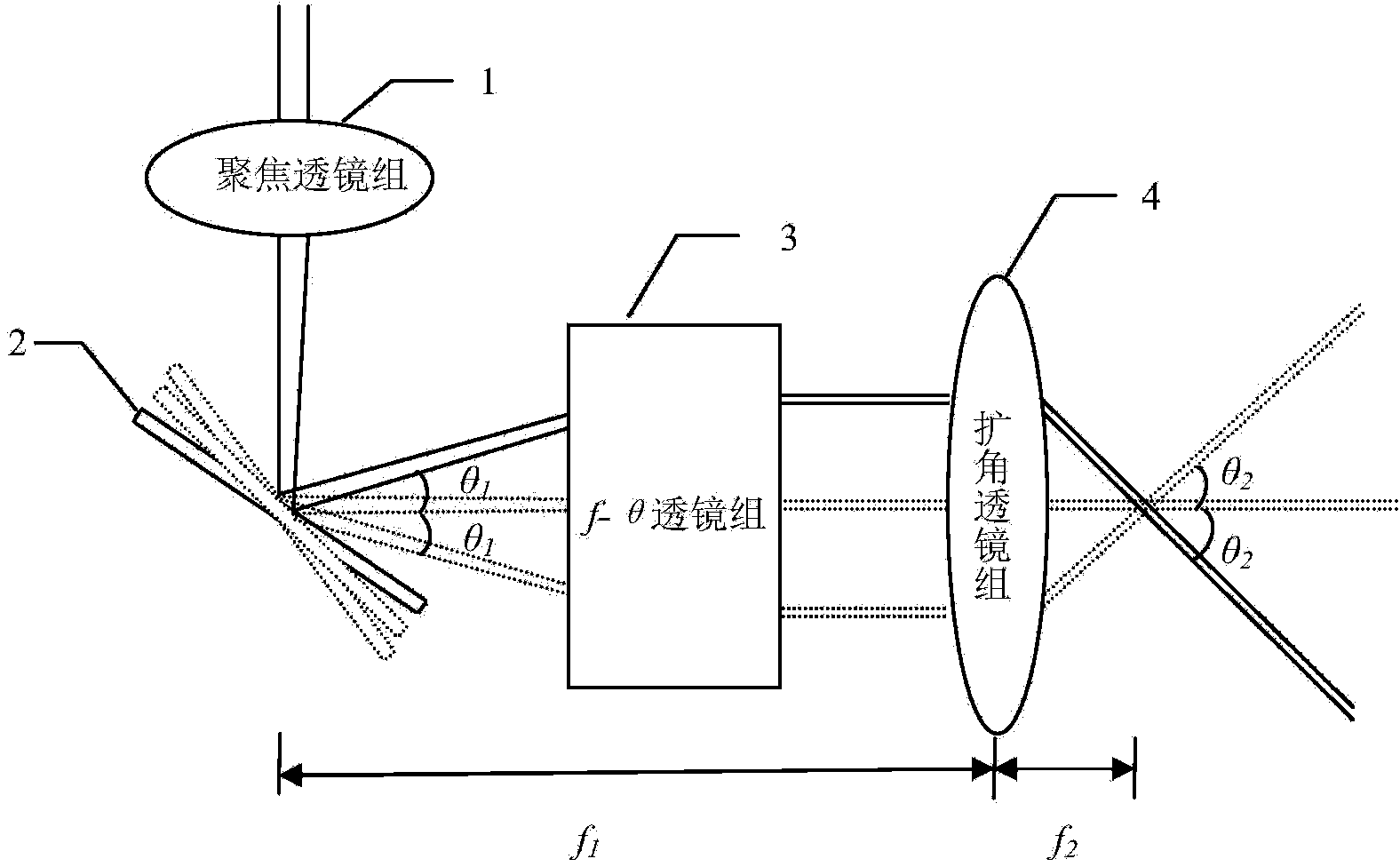
[0024] Specific implementation mode one: see figure 1 Illustrate this embodiment, the MEMS micromirror folding type scanning optical system based on this embodiment, it comprises focusing lens group 1, MEMS micromirror 2, f-θ lens group 3 and angle-expanding lens group 4;

[0025] After the incident light is transmitted by the focusing lens group 1, and then reflected by the MEMS micromirror 2, it enters the f-θ lens group 3, and after being transmitted by the f-θ lens group 3, it enters the angle-expanding lens group 4, and passes through the angle-expanding lens The angle between the transmitted light of group 4 and the optical axis of the system is θ 2 ,and f 2 less than f 1 ;

[0026] Among them, θ 1 is the angle between the light reflected by the MEMS micromirror 2 and the optical axis of the system, f 2 Indicates the effective image square focal length of the expander lens group, f 1 Indicates the focal length of the f-θ lens group 3;

[0027] The mechanical def...

specific Embodiment approach 2

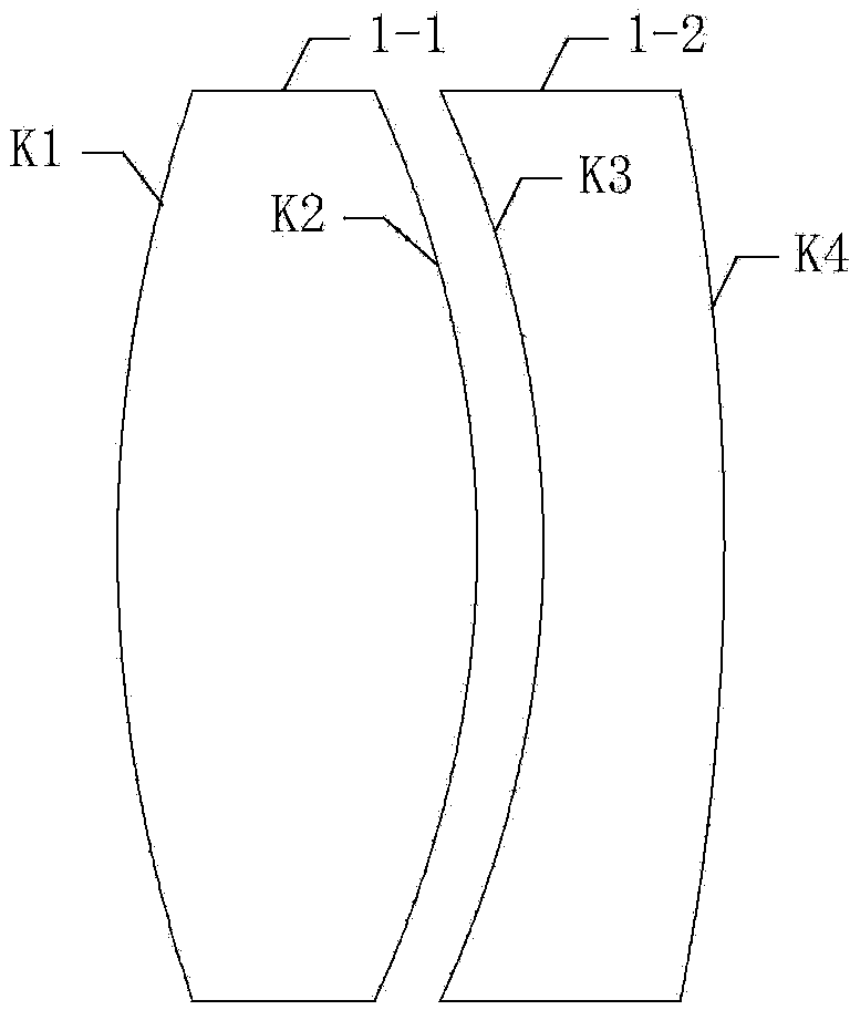
[0039] Specific implementation mode two: see figure 1 with 2 Describe this embodiment, the difference between this embodiment and the MEMS micromirror folded scanning optical system described in the first embodiment is that the focusing lens group 1 is a two-piece front positive lens group, and the two-piece The front positive lens group includes a coaxial No. 1 convex lens 1-1 and a No. 1 concave lens 1-2, and the incident surface of the No. 1 convex lens 1-1 is the incident surface of the two-piece front positive lens group. The materials of the No. 1 convex lens 1-1 and the No. 1 concave lens 1-2 are different, and both are suitable for laser with a wavelength of 1550nm.

[0040] In this embodiment, as figure 2 As shown, the focusing lens group composed of the No. 1 convex lens 1-1 and the No. 1 concave lens 1-2 in front of the MEMS, the focal length of the focusing lens group 1 can be designed to be 100 mm. It consists of two different infrared refractive index materia...

specific Embodiment approach 3

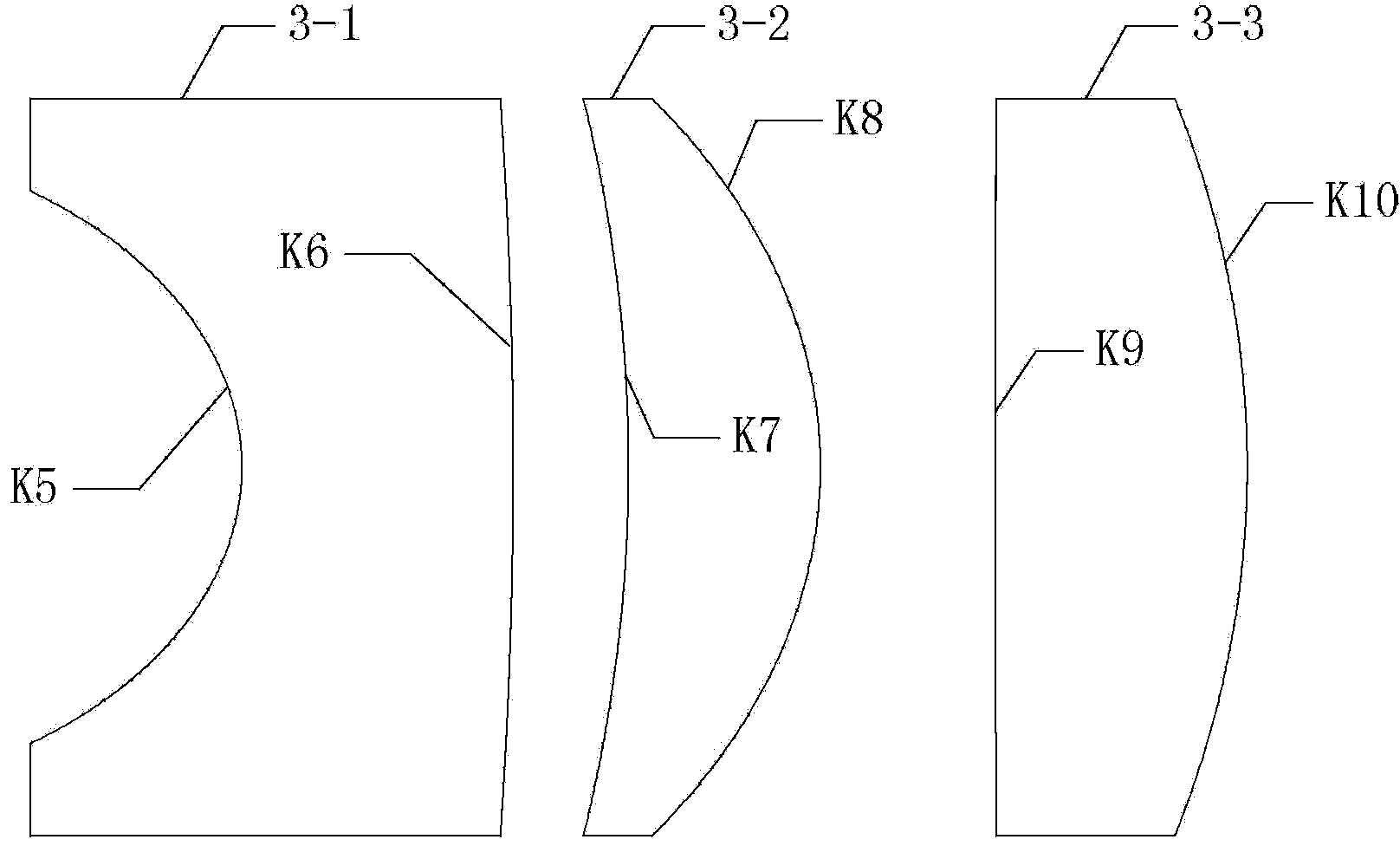
[0041] Specific implementation mode three: see figure 1 with 3 Describe this embodiment, the difference between this embodiment and the MEMS micromirror folded scanning optical system described in the second embodiment is that the f-θ lens group 3 is a three-piece f-θ lens, and the The three-piece f-θ lens includes three coaxial lenses, and the three coaxial lenses are sequentially No. 2 concave lens 3-1, No. 2 convex lens 3-2, No. 3 convex lens 3-3, and 2 The incident surface of No. concave lens 3-1 is the incident surface of f-θ lens group 3.

[0042] In this embodiment, as image 3As shown, the three-piece f-theta lens is composed of three lenses, and the best focal length of the three-piece f-theta lens is 100mm. The three lenses are successively No. 2 concave lens 3-1, No. 2 convex lens 3-2, and No. 3 convex lens 3-3, and their materials are respectively fused silica glass F_SILICA, SF18, and SF18. The lens curve of No. 2 concave lens 3-1 towards the incident beam sid...


PUM


Abstract

The invention provides a folding type scanning optical system based on an MEMS micro mirror, and belongs to the field of optics. The folding type scanning optical system solves the problem that an existing MEMS scanning system is small in the scan field angle. The folding type scanning optical system comprises a focusing lens group, the MEMS micro mirror, an f-theta lens group and an angle expanding lens group. After the incident light is transmitted by the focusing lens group and then is reflected by the MEMS micro mirror, the incident light is irradiated into the f-theta lens group, and is irradiated into the expanding angle lens group after being transmitted by the f-theta lens group, the inclined angle between the transmission light generated after angle expanding is conducted by the angle expanding lens group and a system optical axis is theta 2, and f2 is smaller than f1. Theta 1 serves as the inclined angle between the light reflected by the MEMS micro mirror and the system optical axis, the f2 represents the effective image space focal length of the angle expanding lens group, and the f1 represents the focal length of the f-theta lens group. The mechanical deflection angle of the MEMS micro mirror ranges from -4 degrees to 4 degrees, and the inclined angle theta 1 ranges from -8 degrees to 8 degrees. The folding type scanning optical system based on the MEMS micro mirror is mainly applied to the field of optical scanning.

Description

technical field [0001] The present invention belongs to the field of optics. Background technique [0002] The new generation of lidar systems tends to be smaller in size, lighter in weight and lower in cost, and MEMS scanning plays an important role in this. However, the mechanical deflection angle of the MEMS micromirror is small. In order to achieve a larger scanning field of view, it is generally necessary to increase the angle-expanding optical system. The usual practice is to add a positive lens and a negative lens before and after the MEMS micromirror to form an angle-expanding optical system. However, this simple lens group has at least two disadvantages: [0003] (1) The laser beam emitted from the negative lens is a divergent beam. For a closer target of a few meters, the spot size projected on the target will not be very large; but for a target of tens of meters, hundreds of meters or even farther In other words, the size of the spot projected on the target wil...

Claims


Application Information

Patent Timeline
Patent Type & Authority Applications(China)
IPC IPC(8): G02B26/10
Inventor 王春晖李小宝任逍遥
Owner HARBIN INST OF TECH
Why Eureka
Try Eureka