Supercharge Your Innovation With Domain-Expert AI Agents!

Touch control display panel and display device

A touch display panel and touch signal technology, applied in the direction of instruments, electrical digital data processing, data processing input/output process, etc., can solve the problem of device flatness, difficulty in integrating display devices, increased thickness of display devices, etc. problems, to achieve the effect of avoiding setting and taking into account high precision

Active Publication Date: 2014-12-03
BOE TECH GRP CO LTD
View PDF4 Cites 24 Cited by
  • Summary
  • Abstract
  • Description
  • Claims
  • Application Information

AI Technical Summary

Problems solved by technology

[0002] In the fields of portable reading, portable office equipment, etc., the traditional capacitive touch display panel cannot perform text insertion and editing due to the low precision of capacitive touch, and cannot realize high-precision editing input, which can no longer meet the needs of users for touch display panels. basic needs
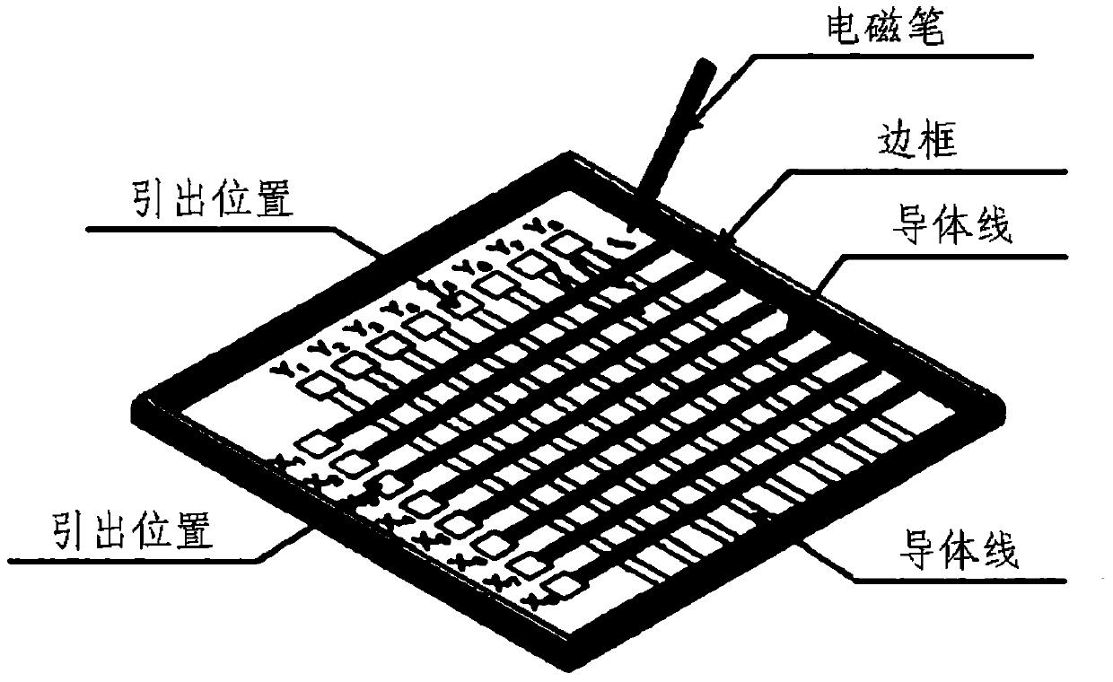
[0003] However, as a high-precision editing input mode, electromagnetic touch is difficult to integrate into display devices that require increasingly thinner and lighter. The main reason is that the most common integration method in the prior art is on the display panel Add a layer of electromagnetic touch panel to realize electromagnetic touch with active electromagnetic pen
However, such an Out-Cell (external) mode not only affects the flatness of the entire device, but also directly leads to an increase in the thickness of the entire display device, which restricts the development of thinner and lighter display devices.

Method used


Image

  • Touch control display panel and display device
  • Touch control display panel and display device
  • Touch control display panel and display device

Examples


Embodiment 1

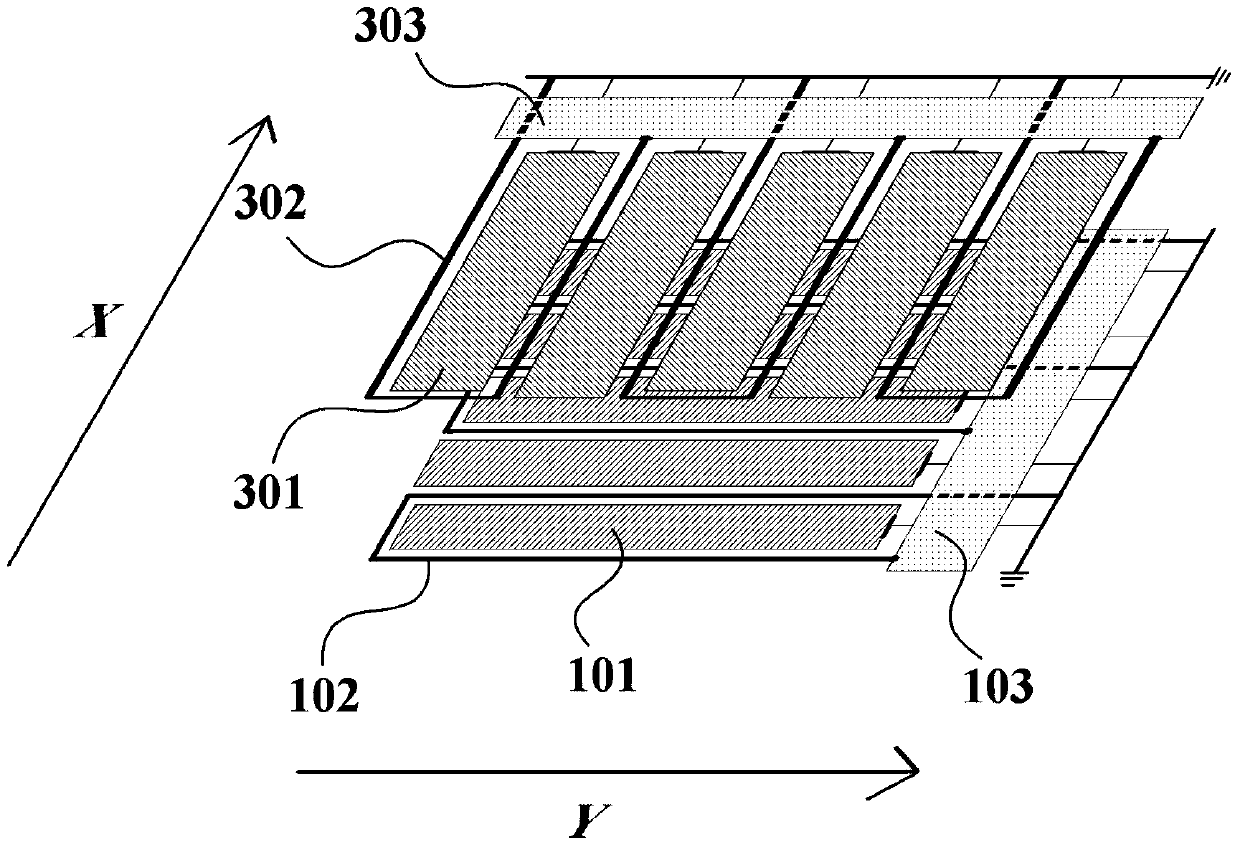
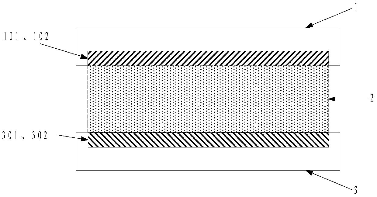
[0040] The embodiment of the present invention proposes a touch display panel, see figure 1 , the touch display panel includes a common electrode 101 and a pixel electrode 301, and the touch display panel further includes a processing module (103 and 303), at least one first magnetic induction electrode 102 and at least one second magnetic induction electrode 302;

[0041] The at least one first magnetic induction electrode 102 is arranged on the same layer as the common electrode 101, and is used to sense the change of the magnetic field in the first direction X and generate a corresponding magnetic induction signal; the at least one second magnetic induction electrode 302 is connected to the The pixel electrode 301 is arranged on the same layer, and is used to sense the change of the magnetic field in the second direction Y and generate a corresponding magnetic induction signal;

[0042] The included angle between the first direction X and the second direction Y is a non-zer...

Embodiment 2

[0067] Based on the same inventive concept, an embodiment of the present invention provides a display device, the display device includes a display panel, and the display panel adopts any touch display panel as described in Embodiment 1. The display device can be any product or component with a display function such as a liquid crystal panel, an electronic paper, an OLED panel, a mobile phone, a tablet computer, a television, a monitor, a notebook computer, a digital photo frame, a navigator, and the like.

[0068] Since the display device provided in the embodiment of the present invention has the same technical features as any touch display panel provided in Embodiment 1, it can also solve the same technical problem and produce the same technical effect.

[0069] To sum up, the present invention first divides the two conductor wires used to sense the magnetic field changes in two different directions in the electromagnetic touch control into the first magnetic induction elect...


PUM


Abstract

The invention relates to the field of touch screen display, and particularly provides a touch control display panel and a display device. The touch control display panel comprises public electrodes, pixel electrodes, processing modules, at least one first magnetic induction electrode and at least one second magnetic induction electrode, wherein the first magnetic induction electrode and the public electrodes are arranged in the same layer; the at least one first magnetic induction electrode is used for sensing magnetic field change in the first direction, and generating corresponding magnetic induction signals; the second magnetic induction electrode and the pixel electrodes are arranged in the same layer; the second magnetic induction electrode is used for sensing magnetic field change in the second direction and generating corresponding magnetic induction signals; the included angle of the first direction and the second direction is a non-zero angle; the processing modules are used for generating touch control signals according to the magnetic induction signals. An electromagnetic touch control function is integrated to the touch control display panel in an In-Cell (built-in) form, and meanwhile high-precision of editing input and lightening and thinning of the whole display device are considered.

Description

technical field [0001] The invention relates to the technical field of touch screen display, in particular to a touch display panel and a display device. Background technique [0002] In the fields of portable reading, portable office equipment, etc., the traditional capacitive touch display panel cannot perform text insertion and editing due to the low precision of capacitive touch, and cannot realize high-precision editing input, which can no longer meet the needs of users for touch display panels. basic needs. [0003] However, as a high-precision editing input mode, electromagnetic touch is difficult to integrate into display devices that require increasingly thinner and lighter. The main reason is that the most common integration method in the prior art is on the display panel Add a layer of electromagnetic touch panel to realize electromagnetic touch with active electromagnetic pen. However, such an Out-Cell (external) mode not only affects the flatness of the entire...

Claims


Application Information

Patent Timeline
IPC IPC(8): G06F3/046
CPCG06F3/046
Inventor 王新星秦广奎
Owner BOE TECH GRP CO LTD
Features
  • R&D
  • Intellectual Property
  • Life Sciences
  • Materials
  • Tech Scout
  • Unparalleled Data Quality
  • Higher Quality Content
  • 60% Fewer Hallucinations
Learn More